
Page 201 - Shale Shakers Drilling Fluid Systems
P. 201
184 SHALE SHAKERS AND DRILLING FLUID SYSTEMS
The actual brake horsepower of a pump is greater discharge line, yields the maximum pressure, or
than the theoretical hydraulic horsepower by the feet of head, which the pump will develop at zero
amount of losses incurred in the pump through flow. The valve is then opened to allow a small
friction, leakage, and so forth. The efficiency of a flow, and the pressure and flow rate are noted.
pump is therefore: The required horsepower (or kilowatts of electric-
ity) is also noted. This process is continued over
the full operating range of the pump. Plotting the
data points reveals the head-capacity and horse-
power curves (Figure 11-1).
and The flow rate from the pump is determined by
the performance and friction curves of the plumb-
ing connected to the pump. The horsepower curves
indicated on a performance curve represent the
power required when pumping water, or any fluid
within the same specific gravity and viscosity as
CENTRIFUGAL PUMP water. Corrections for different specific gravities
PERFORMANCE CURVES are, however, quite straightforward—horsepower is
directly proportional to the specific gravity of the
A pump is a machine that moves a given vol- fluids being pumped. Performance curves are used
ume of liquid a given distance in a period of time. to determine the flow rate, head (pressure) devel-
Pumps take energy from an external source (mo- oped, and horsepower required by a pump having
tor, turbine, etc.) and develop it in the form of dis- a specific diameter impeller and operating at a
charge pressure or total dynamic head. A curve given, constant speed.
can be developed to measure a pump's perfor-
mance. Tests to establish pump performance curves
are run on clear, cold water with a specific grav- Performance Characteristics
ity of 1.0, at 60°F.
To establish a centrifugal pump performance The performance characteristics of a centrifugal
curve, the pump is run in conjunction with a gauge, pump are clearly defined by its performance curve (s).
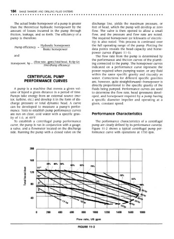
a valve, and a flowmeter located on the discharge Figure 11 -2 shows a typical centrifugal pump per-
side. Running the pump with a closed valve on the formance curve with operations at 1750 rpm.
FIGURE 11-2