
Page 202 - Shale Shakers Drilling Fluid Systems
P. 202
CENTRIFUGAL PUMPS 185
What flow rate is obtained from a centrifugal The flow rate produced by this pump depends on
pump? As stated previously, the flow rate de- what is connected to it.
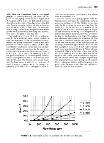
pends on the piping connected to it. Figure 11-3 Friction curves for a piping system with six
shows pipe friction curves for 100 feet of common hydrocyclones connected to a centrifugal pump is
sizes of new steel pipes. This chart shows that 400 presented in Figure 11-5. The friction curves start
gpm flowing through 100 feet of 3-inch diameter with the lift required to move the fluid from the
pipe will cause 33 feet of head loss. The flow rate liquid level in the pits to the centerline of the
from a pump connected to this pipe is determined hydrocyclone manifold. This is the physical height,
by the head generated by the pump and the fric- in feet, measured at the rig. It is independent of
tion loss of the pipe at this flow rate. the flow rate and is, therefore, shown as a horizon-
The head curve (Figure 11 -4) for a particular tal line on the head/flow rate chart. The suction
impeller in a particular pump, would produce a and discharge pipe friction is a function of flow
flow rate dependent on the friction curve that rep- rate and is plotted as a curve above the lift "line."
resents the piping connected to the pump. This At the flow rate required for the hydrocyclones, the
performance curve shows a small lift head re- discharge and suction pipe frictions are calculated,
quired before the friction curves start. If a substan- For example, if these were 4-inch hydrocyclones,
tial length of pipe is connected to the pump, the each cone would accept 50 gpm if 75 feet of head
friction curve intersects the head curve at point I, is applied. This is a function of the size of the
or 400 gpm. This is called the operating point. If nozzle or opening size on the input side of the
less pipe is connected to the same pump, the fric- hydrocyclone. Since there are six cones in paral-
tion head (or pressure) loss is lower for any flow lei, the friction curves are arranged sequentially,
rate. In this case, the friction curve would inter- The appropriate head (accounting for lift, suction
sect the head curve at point II, or 1000 gpm. If friction, discharge friction, and hydrocyclones), to-
much less pipe is connected to the pump, the gether with the appropriate flow rate, will deter-
operating point will move to 1400 gpm at point III. mine the impeller size required.
FIGURE 11-3. Pipe friction curves for common sizes of 100' new steel pipe.