
Page 221 - Shale Shakers Drilling Fluid Systems
P. 221
ELECTRIC MOTORS 203
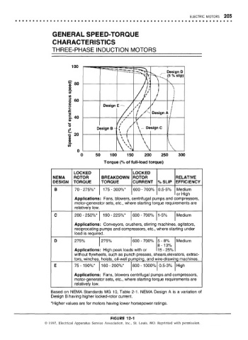
GENERAL SPEED-TORQUE
CHARACTERISTICS
THREE-PHASE INDUCTION MOTORS
LOCKED LOCKED
NEMA ROTOR BREAKDOWN ROTOR RELATIVE
DESIGN TORQUE TORQUE CURRENT % SLIP EFFICIENCY
B 70 - 275%* 175-300%* 600 - 700% 0.5-5% Medium
or High
Applications: Fans, blowers, centrifugal pumps and ccompressors,
motor-generator sets, etc., whe jre starting torque requirements are
relatively low.
C 200 - 250%* 190-225%* 600 - 700% 1-5% Medium
Applications: Conveyors, crushers, stirring machines , agitators,
reciprocating pumps and compressors, etc., where starting under
load is require3d.
D 275% 275% 600 - 700% 5 - 8% Medium
8 - 1 3%
Applications: High peak loads with or 15-25%
without flywh€jels, such as punDh presses, sriears,elevators, extrac-
tors, winches hoists, oil-well pijmping, and w/ire-drawirig machines.
E 75-190%* 160-200%* 1 800 -1000% 0.5-3% High
Applications: Fans, blowers centrifugal purnps and compressors,
motor-generator sets, etc., where starting tor que requirements are
relatively low.
Based on NEMA Standards MG 10, Table 2-1. NEMA Design A is a variation of
Design B having higher locked-rotor current.
*Higher values are for motors having lower horsepower ratings.
FIGURE 12-1
© 1997, Electrical Apparatus Service Association, Inc., St. Louis, MO. Reprinted with permission.