
Page 225 - Shale Shakers Drilling Fluid Systems
P. 225
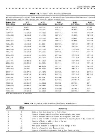
ELECTRIC MOTORS  207


                                   TABLE 12-3. IEC Versus NEMA Mounting Dimensions

        For foot-mounted motors, the IEC frame designation consists of the shaft height followed by the shaft extension expressed
        in millimeters, while the NEMA system uses a specific number for each frame.
        Frame Size            H/D              A/2E               B/2F              C/BA              K/H
        IEC/NEMA           IEC/NEMA          IEC/NEMA          IEC/NEMA           IEC/NEMA         IEC/NEMA
        90S/143             90/86.9           140/139.7         100/101.6          56/57.2           10/8.6
        90L/145             90/88.9           140/139.7         125/127            56/57.2           10/8.6

        112S/180            H2/H4.3           190/190.5         114/114.3          70/69.9           12/10.4
        112M/184            112/114. 3        190/190.5         140/139.7          89/88.9           12/10.4

        132S/213            132/133.4        216/215.9          140/139.7          89/88.9           12/10.4
        132M/216            132/133.4        216/215.9          178/177.8          89/88.9           12/10.4

        160M/254            160/158.8        254/254            210/209.5          108/108           15/13.5
        160L/256            160/158.8        254/254            254/254            108/108           15/13.5

        180M/284            180/177.8        279/279.4          241/241.3          121/120.6         15/13.5
        180L/286            180/177.8        279/279.4          279/279.4          121/120.6         15/13.5

        200M/324            200/203.2        318/317.5          267/266.7          133/133.4         19/16.8
        200L/326            200/203.2        318/317.5          305/304.8          133/133.4         19/16.8

        225S/364            225/228.6        356/355.6          286/285.8          149/149.4         19/16.8
        225M/365            225/228.6        356/355.6          311/311.1          149/149.4         19/16.8

        250S/404            250/254          406/406.4          311/311.2          168/168.1        24/20.6
        250M/405            250/254          406/406.4          349/349.2          168/168.1        24/20.6

        280S/444            280/279.4        457/457.2          368/368.3          190/190.5        24/20.6
        280M/445            280/279.4        457/457.2          419/419.1          190/190.5        24/20.6

        315S/504            315/317.5        508/508            406/406.4         216/215.9         28/—
        315M/505            315/317.5        508/508            457/457.2         216/215.9         28/—

        355S/585            355/368.3        610/584.2          500/508           254/254           28/—
        355M/586            355/368.3        610/584.2          560/558.8         254/254           28/—

        400S/684            400/431.8        686/685.8          560/558.8         280/292.1         35/—
        400M/685            400/431.8        686/685.8          630/635           280/292.1         35/—
        Note: All dimensions are in millimeters.


                            TABLE 12-4. IEC Versus NEMA Mounting Dimensions Nomenclature

         IEC           NEMA
        Letter         Letter                                       Dimension
          H              D           Distance from shaft centerline to foot bottom
          A             2E           Distance between centerlines of foot mounting holes (end view)
          B             2F           Distance between centerlines of foot mounting holes (side view)
          C             BA           Distance from shoulder on shaft to centerline of mounting holes in the nearest feet
          K              H           Diameter of holes or width of slots in the feet
          D              U           Diameter of shaft extension
          M             AJ           Pitch circle diameter of fixing holes in face, flange, or base
          N             AK           Diameter of spigot on face, flange, or base
          S             BF           Diameter of threaded or clearance hole in face, flange, or base