
Page 246 - Shale Shakers Drilling Fluid Systems
P. 246
228 SHALE SHAKERS AND DRILLING FLUID SYSTEMS
impeller blades in a centrifugal pump, which See item 12.
propel the fluid outward. Both types are de-
signed to move all of the fluid within a certain 16. Mud guns can be used in the Addition and Check/
volume. The turnover rate (TOR) depends on Suction Sections of the surface system and pro-
how much fluid is moving. The TOR must vide the benefits of shear and dividing and re-
be large enough to adequately blend the fluid blending newly added mud materials.
within the compartment. TOR is calculated as Mud guns do an excellent job of shearing new
60 times the tank volume divided by displace- material enabling it to disperse, and are effec-
ment. Displacement or flow rate associated tive at blending new material into the surface
with each type of blade, based on projected system. Agitators may aid and assist mud guns
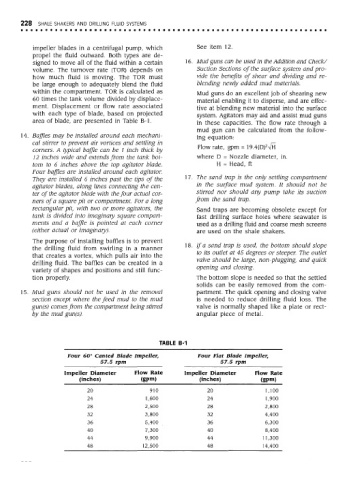
area of blade, are presented in Table B-l. in these capacities. The flow rate through a
mud gun can be calculated from the follow-
14. Baffles may be installed around each mechani- ing equation:
cal stirrer to prevent air vortices and settling in 2
corners. A typical baffle can be 1 inch thick by Flow rate, gpm = 19.4(D) VH
12 inches wide and extends from the tank bot- where D = Nozzle diameter, in.
tom to 6 inches above the top agitator blade. H = Head, ft
Four baffles are installed around each agitator.
They are installed 6 inches past the tips of the 17. The sand trap is the only settling compartment
agitator blades, along lines connecting the cen- in the surface mud system. It should not be
ter of the agitator blade with the four actual cor- stirred nor should any pump take its suction
ners of a square pit or compartment. For a long from the sand trap.
rectangular pit, with two or more agitators, the Sand traps are becoming obsolete except for
tank is divided into imaginary square compart- fast drilling surface holes where seawater is
ments and a baffle is pointed at each corner used as a drilling fluid and coarse mesh screens
(either actual or imaginary). are used on the shale shakers.
The purpose of installing baffles is to prevent
the drilling fluid from swirling in a manner 18. If a sand trap is used, the bottom should slope
that creates a vortex, which pulls air into the to its outlet at 45 degrees or steeper. The outlet
drilling fluid. The baffles can be created in a valve should be large, non-plugging, and quick
variety of shapes and positions and still func- opening and closing.
tion properly. The bottom slope is needed so that the settled
solids can be easily removed from the com-
15. Mud guns should not be used in the removal partment. The quick opening and closing valve
section except where the feed mud to the mud is needed to reduce drilling fluid loss. The
gun(s) comes from the compartment being stirred valve is normally shaped like a plate or rect-
by the mud gun(s). angular piece of metal.
TABLE B-1
Four 6O° Canted Blade Impeller, Four Flat Blade Impeller,
57.5 rpm 57.5 rpm
Impeller Diameter Flow Rate Impeller Diameter Flow Rate
(inches) (gpm) (inches) (gpm)
20 910 20 1,100
24 1,600 24 1,900
28 2,500 28 2,800
32 3,800 32 4,400
36 5,400 36 6,300
40 7,300 40 8,400
44 9,900 44 11,300
48 12,500 48 14,400