
Page 440 - Shigley's Mechanical Engineering Design
P. 440
bud29281_ch08_409-474.qxd 12/16/2009 7:11 pm Page 415 pinnacle 203:MHDQ196:bud29281:0073529281:bud29281_pagefiles:
Screws, Fasteners, and the Design of Nonpermanent Joints 415
Figure 8–5
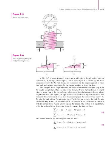
Portion of a power screw.
d m
F
p
Nut
F⁄ 2 F⁄ 2
Figure 8–6 y y
Force diagrams: (a) lifting the
load; (b) lowering the load. F F
fN
P R
l x fN l x
P L
N N
d m d m
(a) (b)
In Fig. 8–5 a square-threaded power screw with single thread having a mean
diameter d m , a pitch p, a lead angle λ, and a helix angle ψ is loaded by the axial
compressive force F. We wish to find an expression for the torque required to raise
this load, and another expression for the torque required to lower the load.
First, imagine that a single thread of the screw is unrolled or developed (Fig. 8–6)
for exactly a single turn. Then one edge of the thread will form the hypotenuse of a right
triangle whose base is the circumference of the mean-thread-diameter circle and whose
height is the lead. The angle λ, in Figs. 8–5 and 8–6, is the lead angle of the thread. We
represent the summation of all the axial forces acting upon the normal thread area by F.
To raise the load, a force P R acts to the right (Fig. 8–6a), and to lower the load, P L acts
to the left (Fig. 8–6b). The friction force is the product of the coefficient of friction f
with the normal force N, and acts to oppose the motion. The system is in equilibrium
under the action of these forces, and hence, for raising the load, we have
F x = P R − N sin λ − fN cos λ = 0
(a)
F y =−F − fN sin λ + N cos λ = 0
In a similar manner, for lowering the load, we have
F x =−P L − N sin λ + fN cos λ = 0
(b)
F y =−F + fN sin λ + N cos λ = 0