
Page 37 -
P. 37
8 PART ONE THE PRODUCT AND THE PROCESS
FIGURE 1.2
Increased failure
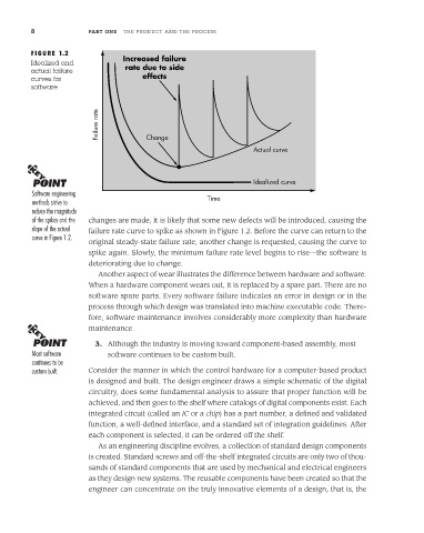
Idealized and
actual failure rate due to side
curves for effects
software
Failure rate
Change
Actual curve
Idealized curve
Software engineering
methods strive to Time
reduce the magnitude
of the spikes and the changes are made, it is likely that some new defects will be introduced, causing the
slope of the actual failure rate curve to spike as shown in Figure 1.2. Before the curve can return to the
curve in Figure 1.2.
original steady-state failure rate, another change is requested, causing the curve to
spike again. Slowly, the minimum failure rate level begins to rise—the software is
deteriorating due to change.
Another aspect of wear illustrates the difference between hardware and software.
When a hardware component wears out, it is replaced by a spare part. There are no
software spare parts. Every software failure indicates an error in design or in the
process through which design was translated into machine executable code. There-
fore, software maintenance involves considerably more complexity than hardware
maintenance.
3. Although the industry is moving toward component-based assembly, most
Most software software continues to be custom built.
continues to be
custom built. Consider the manner in which the control hardware for a computer-based product
is designed and built. The design engineer draws a simple schematic of the digital
circuitry, does some fundamental analysis to assure that proper function will be
achieved, and then goes to the shelf where catalogs of digital components exist. Each
integrated circuit (called an IC or a chip) has a part number, a defined and validated
function, a well-defined interface, and a standard set of integration guidelines. After
each component is selected, it can be ordered off the shelf.
As an engineering discipline evolves, a collection of standard design components
is created. Standard screws and off-the-shelf integrated circuits are only two of thou-
sands of standard components that are used by mechanical and electrical engineers
as they design new systems. The reusable components have been created so that the
engineer can concentrate on the truly innovative elements of a design, that is, the