
Page 185 - Solar Power in Building Design The Engineer's Complete Design Resource
P. 185
COMPUTERIZED LIGHTING CONTROL 155
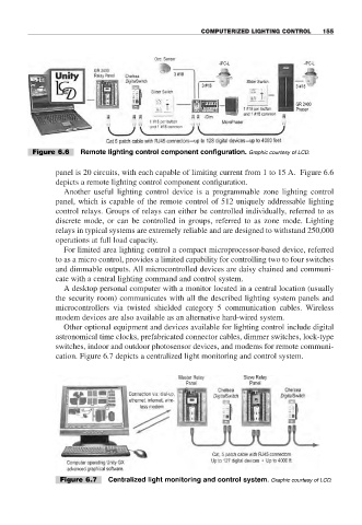
Figure 6.6 Remote lighting control component configuration. Graphic courtesy of LCD.
panel is 20 circuits, with each capable of limiting current from 1 to 15 A. Figure 6.6
depicts a remote lighting control component configuration.
Another useful lighting control device is a programmable zone lighting control
panel, which is capable of the remote control of 512 uniquely addressable lighting
control relays. Groups of relays can either be controlled individually, referred to as
discrete mode, or can be controlled in groups, referred to as zone mode. Lighting
relays in typical systems are extremely reliable and are designed to withstand 250,000
operations at full load capacity.
For limited area lighting control a compact microprocessor-based device, referred
to as a micro control, provides a limited capability for controlling two to four switches
and dimmable outputs. All microcontrolled devices are daisy chained and communi-
cate with a central lighting command and control system.
A desktop personal computer with a monitor located in a central location (usually
the security room) communicates with all the described lighting system panels and
microcontrollers via twisted shielded category 5 communication cables. Wireless
modem devices are also available as an alternative hard-wired system.
Other optional equipment and devices available for lighting control include digital
astronomical time clocks, prefabricated connector cables, dimmer switches, lock-type
switches, indoor and outdoor photosensor devices, and modems for remote communi-
cation. Figure 6.7 depicts a centralized light monitoring and control system.
Figure 6.7 Centralized light monitoring and control system. Graphic courtesy of LCD.