
Page 165 - Standard Handbook Petroleum Natural Gas Engineering VOLUME2
P. 165
134 Reservoir Engineering
(text continued from page 130)
The tools work well in low-resistivity formations with thick beds and in slightly
conductive muds.
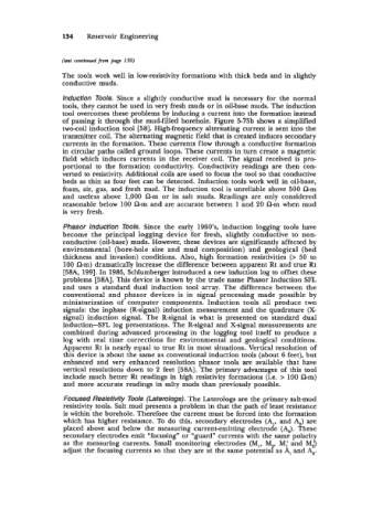
lnduction Tools. Since a slightly conductive mud is necessary for the normal
tools, they cannot be used in very fresh muds or in oil-base muds. The induction
tool overcomes these problems by inducing a current into the formation instead
of passing it through the mud-filled borehole. Figure 5-7513 shows a simplified
two-coil induction tool [58]. High-frequency alternating current is sent into the
transmitter coil. The alternating magnetic field that is created induces secondary
currents in the formation. These currents flow through a conductive formation
in circular paths called ground loops. These currents in turn create a magnetic
field which induces currents in the receiver coil. The signal received is pro-
portional to the formation conductivity. Conductivity readings are then con-
verted to resistivity. Additional coils are used to focus the tool so that conductive
beds as thin as four feet can be detected. Induction tools work well in oil-base,
foam, air, gas, and fresh mud. The induction tool is unreliable above 500 a-m
and useless above 1,000 am or in salt muds. Readings are only considered
reasonable below 100 a-m and are accurate between 1 and 20 am when mud
is very fresh.
Phasor lnduction TOOIS. Since the early 1960’s, induction logging tools have
become the principal logging device for fresh, slightly conductive to non-
conductive (oil-base) muds. However, these devices are significantly affected by
environmental (bore-hole size and mud composition) and geological (bed
thickness and invasion) conditions. Also, high formation resistivities (> 50 to
100 a-m) dramatically increase the difference between apparent Rt and true Rt
[58A, 1991. In 1986, Schlumberger introduced a new induction log to offset these
problems [58A]. This device is known by the trade name Phasor Induction SFL
and uses a standard dual induction tool array. The difference between the
conventional and phasor devices is in signal processing made possible by
miniaturization of computer components. Induction tools all produce two
signals: the inphase (R-signal) induction measurement and the quadrature (X-
signal) induction signal. The R-signal is what is presented on standard dual
inductionSFL log presentations. The R-signal and X-signal measurements are
combined during advanced processing in the logging tool itself to produce a
log with real time corrections for environmental and geological conditions.
Apparent Rt is nearly equal to true Rt in most situations. Vertical resolution of
this device is about the same as conventional induction tools (about 6 feet), but
enhanced and very enhanced resolution phasor tools are available that have
vertical resolutions down to 2 feet [58A]. The primary advantages of this tool
include much better Rt readings in high resistivity formations (i.e. > 100 a-m)
and more accurate readings in salty muds than previously possible.
Focused Resistivity Tools (Laferologs). The Laterologs are the primary salt-mud
resistivity tools. Salt mud presents a problem in that the path of least resistance
is within the borehole. Therefore the current must be forced into the formation
which has higher resistance. To do this, secondary electrodes (A,, and 4) are
placed above and below the measuring current-emitting electrode (AJ. These
secondary electrodes emit “focusing” or “guard” currents with the same polarity
as the measuring currents. Small monitoring electrodes (MI, M,, M,’ and Me?
adjust the focusing currents so that they are at the same potential as A, and 4.