Page 491 - Standard Handbook Petroleum Natural Gas Engineering VOLUME2
P. 491
Flow  of  Fluids   447

                  (text continued f+om pap 437)


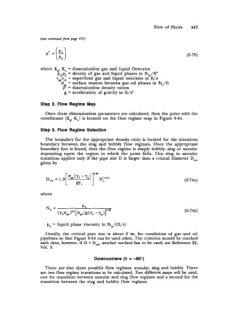
                     p'=(k)                                                      (6-73)


                  where K,, K, = dimensionless gas and liquid flowrates
                          p  p  = density of  gas and liquid phases in lbm/ft3
                         v:vs:   = superficial gas and liquid velocities in ft/s
                              = surface tension between gas-oil  phases in lbf/ft
                           3 dimensionless density ration
                              =
                             g = acceleration of  gravity in ft/s2
                  Step 2.  Flow Regime Map

                    Once these dimensionless parameters are calculated, then the point with the
                  coordinates (K,,  KJ  is located on the flow regime map in Figure 6-44.

                  Step 3.  Flow Regime Selection

                    The boundary for the appropriate density ratio is located for the transition
                  boundary between  the  slug and  bubbly  flow regimes.  Once  the  appropriate
                  boundary line is found, then the flow regime is simply bubbly, slug or annular
                  depending  upon  the  region  in  which  the  point  falls. This  slug to  annular
                  transition applies only if  the pipe size D is larger than a critical diameter D,r
                  given by


                                                                                (6-744

                  where


                                                                                (6-74b)

                     pL = liquid phase viscosity in lbJ(ft/s)

                    Usually,  the  critical pipe  size is. about  2  in.  for  conditions  of  gas  and  oil
                  pipelines so  that Figure 644 can be used often. The criterion should be checked
                  each time, however.-If  D < Dc, another method has to be used; see Reference 22,
                  VOl.  3.

                                         Downcomers (0 = -90")

                    There are also three possible flow regimes: annular, slug and bubbly. There
                  are two flow regime transitions to be calculated. Two different maps will be used,
                  one for transition between annular and slug flow regimes and a second for the
                  transition between the slug and bubbly flow regimes.

