
Page 493 - Standard Handbook Petroleum Natural Gas Engineering VOLUME2
P. 493
Flow of Fluids 449
Annular-Slug Transition
1. Dimensionless parameters X and I Y I from EQuation 64% and 6-70, respectively.
2. Flow regime map, see Figure 6-45.
3. Flow regime selection. Locate the point with (X, IY I) COOI-~~M~~S; point
the
if
falls in the region %nnular,’’ then the flow regime is annular. If the point falls
in region “slug” or “bubbly,” then the map from Figure 6-47 must be used.
Slug-Bubbly Transition
1. Calculate dimensionless parameters K,, K, and p*; use Equations 672 and
6-73, respectively.
2. The appropriate regime boundary for the specific weight ratio is selected
on the regime map with K,, K, coordinates.
3. Flow regime selection. Depending upon which region of the map the data
point falls into, flow regime is slug or bubbly.
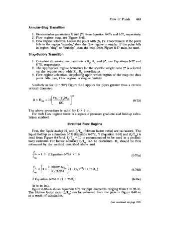
Similarly as for (9 = 90’) Figure 6-46 applies for pipes greater than a certain
critical diameter.
(6-75)
The above procedure is valid for D > 2 in.
For each flow regime there is a separate pressure gradient and holdup calcu-
lation method.
Stratified Flow Regime
First, the liquid holdup H, and fi/f (friction factor ratio) are calculated. The
liquid holdup as a function of X (Equsion 667u), Y (Equation 6-70) and (fJf-) is
read from Figure 647~-d. fi/fw = 10 is recommended to be used as a prelimi-
nary estimate. For better accuracy f/L can be calculated. H, should be first
estimated by the method described above and
fi = 1.0 if Equation 6-766 < 1.0 (6-76~)
f ,
1
fi= 0-000025Re~ (1 - HL)5/*(1 + 75HL)
f * [ + D / 3.281 (6-766)
if Equation 6-766 > (1 + 75H,) (6-76~)
(D is in in.).
Figure 6-48a-fi shows Equation 6-76 for pipe diameters ranging from 4 to 36 in.
The friction factor ratio (EJfv8) can be estimated hm the plots in Figure 648 or
as a result of calculation.
(texi continued on page 464)