
Page 74 - Steam Turbines--Design, Applications, and Rerating by Heinz-Bloch, Murari-Singh
P. 74
Bearings for Mechanical Drive Turbines 55
the bearing eccentricity ratio ε is very large, and the attitude angle ψ
approaches 0°. In this manner, a heavy −Y direction load is supported
by a Y displacement. This occurs because the load is so heavy and the
resulting pressure profile becomes very large, with large gradients
from the maximum film to the minimum film locations. From a force
summation ΣF x = 0 and ΣF y = W. This can occur only for attitude angles
that approach 0°. Since a downward load is now supported by a verti-
cal displacement, cross-coupling forces are at a minimum and the bear-
ing is stable.
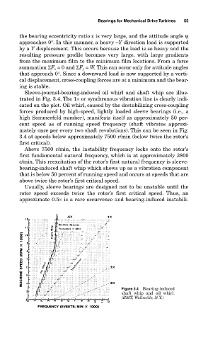
Sleeve-journal-bearing-induced oil whirl and shaft whip are illus-
trated in Fig. 3.4. The 1× or synchronous vibration line is clearly indi-
cated on the plot. Oil whirl, caused by the destabilizing cross-coupling
forces produced by high-speed, lightly loaded sleeve bearings (i.e., a
high Sommerfeld number), manifests itself as approximately 50 per-
cent speed as of running speed frequency (shaft vibrates approxi-
mately once per every two shaft revolutions). This can be seen in Fig.
3.4 at speeds below approximately 7500 r/min (below twice the rotor’s
first critical).
Above 7500 r/min, the instability frequency locks onto the rotor’s
first fundamental natural frequency, which is at approximately 3800
c/min. This reexcitation of the rotor’s first natural frequency is sleeve-
bearing-induced shaft whip which shows up as a vibration component
that is below 50 percent of running speed and occurs at speeds that are
above twice the rotor’s first critical speed.
Usually, sleeve bearings are designed not to be unstable until the
rotor speed exceeds twice the rotor’s first critical speed. Thus, an
approximate 0.5× is a rare occurrence and bearing-induced instabili-
Figure 3.4 Bearing-induced
shaft whip and oil whirl.
(RMT, Wellsville, N.Y.)