
Page 75 - Steam Turbines--Design, Applications, and Rerating by Heinz-Bloch, Murari-Singh
P. 75
56 Chapter Three
ties usually show up as shaft whip at frequencies less than 50 percent
of synchronous speed.
Axial groove bearings have a cylindrical bore with typically two to
four axial oil feed grooves. These bearings have been very popular in
relatively low-speed steam turbines. For a given bearing load mag-
nitude and orientation, the stability characteristics of axial groove
bearings are controlled primarily by the bearing clearance. Tight
clearances produce higher instability thresholds but tight clearance
bearings present other problems that make them undesirable. For
example, as clearance decreases, the bearing’s operating oil tempera-
ture increases. Furthermore, babbitt wear during repeated start-ups
will increase the bearing’s clearance, thereby degrading stability. In
fact, many bearing-induced instabilities in the field are caused by bear-
ing clearances that have increased due to wear from oil contamination,
repeated starts, or slow-rolling with boundary lubrication.
Because of these limitations, other fixed-bore bearing designs have
evolved to counteract some of the poor stability characteristics of axial
groove bearings. Some antiwhirl sleeve bearing examples include pres-
sure dam bearings, offset half bearings, and multilobe bearings. These
bearing designs have been successful in increasing the instability
threshold speed compared to axial groove bearings. The pressure dam
bearing is probably the most popular with steam turbine designers and
is still being used today in some lower-speed applications.
3.1.2 Tilting-pad journal bearings
Even though they are costlier than fixed-geometry bearings, tilting-
pad journal bearings have gained popularity with steam turbine
designers because of their superior stability performance. Unlike fixed-
geometry bearings, tilt-pad bearings generate very little destabilizing
cross-coupled stiffness regardless of geometry, speed, load, or operating
eccentricity. However, turbines supported on tilting-pad bearings are
still susceptible to instabilities due to other components within the
machine such as labyrinth seals and/or the turbine blades (steam
whirl).
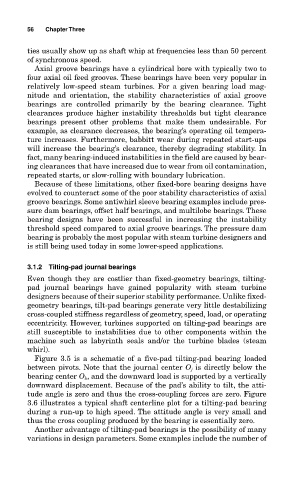
Figure 3.5 is a schematic of a five-pad tilting-pad bearing loaded
between pivots. Note that the journal center O j is directly below the
bearing center O b , and the downward load is supported by a vertically
downward displacement. Because of the pad’s ability to tilt, the atti-
tude angle is zero and thus the cross-coupling forces are zero. Figure
3.6 illustrates a typical shaft centerline plot for a tilting-pad bearing
during a run-up to high speed. The attitude angle is very small and
thus the cross coupling produced by the bearing is essentially zero.
Another advantage of tilting-pad bearings is the possibility of many
variations in design parameters. Some examples include the number of