
Page 180 - Steam Turbines Design, Applications, and Rerating
P. 180
Couplings and Coupling Considerations 159
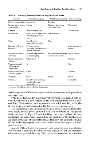
TABLE 9.1 Coupling Selection Criteria for Major Turbomachinery
Feature Gear type coupling Diaphragm coupling Solid coupling
Power transmission Line contact Friction
Limitation of power Limited Limited, depending Unlimited
and speed on conditions
Erection Great care required Normal care
Lubrication Very clean oil. Problems Not required
with high peripheral
speeds
Wear Possible if not None
assembled correctly
Number of thrust Separate thrust Only one thrust
bearings bearings for turbine and bearing
driven machine
Loading of thrust Influenced by friction Influence of diaphragm Well-defined
bearing in the coupling deflection possible
Balancing of axial Not possible Possible
thrust
Transmission of No Yes
differential
expansion
Mutual effect upon Slight Normal
critical speeds
Windage Small Large Small
Unbalance Possible if not correctly Negligible
machined and/or
assembled
SOURCE: Asea Brown-Boveri, Baden, Switzerland
Axial alignment of the train requires the same conventional procedure
and expertise.
With direct turbine drive, normally the turbine is equipped with its
own thrust bearing and coupled to the compressor train with a gear
coupling. Compressors and expanders are solid coupled, with the
thrust bearing usually located in the low-pressure compressor.
If an intermediate gear is necessary, one manufacturer (Sulzer) often
uses single helical gears provided with thrust collars on the pinion
shaft as shown in Figs. 9.3 and 9.4. Here, the thrust collars not only
neutralize the axial thrust created by the meshing of the teeth cut at
an angle to the axis of the shaft but also transmit the unbalanced axial
thrust of the high-speed rotor train to the thrust bearing on the low-
speed section.
Because of the oil film, the pressure zone is spread over an enlarged
surface with a pressure distribution very similar to that of a standard
oil-lubricated journal bearing. The thrust transmission is therefore