
Page 181 - Steam Turbines Design, Applications, and Rerating
P. 181
160 Chapter Nine
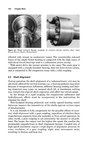
Figure 9.2 Rigid (integral flange) coupling on reaction stream turbine rotor. (Asea
Brown-Boveri, Baden, Switzerland)
effected with almost no mechanical losses. The considerably reduced
losses of the single thrust bearing as compared with the high losses of
individual thrust bearings lead to a substantial power saving.
With motor drive the normal practice is the same. The main gear is
equipped with a simple shoulder bearing, does not have thrust collars,
and is connected to the compressor train with a solid coupling.
9.2 Shaft Alignment
During operation the shaft alignment of a turbomachinery unit may be
adversely affected for several reasons, e.g., a bearing pedestal may grow
because of temperature influences; different bearing loading and bear-
ing diameters may cause an unequal shaft lift; or foundation settling
may disturb the original shaft alignment and affect the critical speed.
In the design of a rigid coupling the temperature influences and
hydrodynamic effects must be incorporated in the instructions for
aligning the shaft.
Well-designed bearing pedestals and widely spaced bearing center
distances improve the insensitivity of the shafts against various types
of misalignment.
It is not feasible to fully compensate for the possible effects of incor-
rect shaft alignment with a gear coupling, regardless of whether these
imperfections originate from site assembly or from actual operation. In
other words, a gear coupling is not necessarily the answer to all prob-
lems. The larger the output and the higher the speed, the smaller the
permissible imperfections in shaft alignment become. Coupled sets of
high-speed machinery require a high degree of alignment accuracy. At
every revolution of a gear coupling slight axial movements occur,
resulting in friction and heat rise.