
Page 267 - Steam Turbines Design, Applications, and Rerating
P. 267
246 Chapter Thirteen
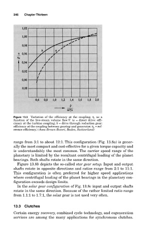
Figure 13.3 Variation of the efficiency at the coupling, η, as a
˙
function of the live-steam volume flow V. (a = direct drive: effi-
ciency at the turbine coupling; b = drive through reduction gear:
efficiency at the coupling between gearing and generator; η o = ref-
erence efficiency.) (Asea Brown-Boveri, Baden, Switzerland)
range from 3:1 to about 12:1. This configuration (Fig. 13.8a) is gener-
ally the most compact and cost-effective for a given torque capacity and
is understandably the most common. The carrier speed range of the
planetary is limited by the resultant centrifugal loading of the planet
bearings. Both shafts rotate in the same direction.
Figure 13.8b depicts the so-called star gear setup. Input and output
shafts rotate in opposite directions and ratios range from 2:1 to 11:1.
This configuration is often preferred for higher speed applications
where centrifugal loading of the planet bearings in the planetary con-
figuration exceeds design limits.
In the solar gear configuration of Fig. 13.8c input and output shafts
rotate in the same direction. Because of the rather limited ratio range
from 1.1:1 to 1.7:1, the solar gear is not used very often.
13.3 Clutches
Certain energy recovery, combined cycle technology, and cogeneration
services are among the many applications for synchronous clutches.