
Page 270 - Steam Turbines Design, Applications, and Rerating
P. 270
Transmission Elements for High-Speed Turbomachinery 249
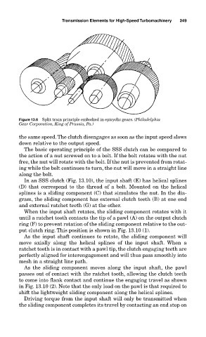
Figure 13.6 Split train principle embodied in epicyclic gears. (Philadelphia
Gear Corporation, King of Prussia, Pa.)
the same speed. The clutch disengages as soon as the input speed slows
down relative to the output speed.
The basic operating principle of the SSS clutch can be compared to
the action of a nut screwed on to a bolt. If the bolt rotates with the nut
free, the nut will rotate with the bolt. If the nut is prevented from rotat-
ing while the bolt continues to turn, the nut will move in a straight line
along the bolt.
In an SSS clutch (Fig. 13.10), the input shaft (E) has helical splines
(D) that correspond to the thread of a bolt. Mounted on the helical
splines is a sliding component (C) that simulates the nut. In the dia-
gram, the sliding component has external clutch teeth (B) at one end
and external ratchet teeth (G) at the other.
When the input shaft rotates, the sliding component rotates with it
until a ratchet tooth contacts the tip of a pawl (A) on the output clutch
ring (F) to prevent rotation of the sliding component relative to the out-
put clutch ring. This position is shown in Fig. 13.10 (1).
As the input shaft continues to rotate, the sliding component will
move axially along the helical splines of the input shaft. When a
ratchet tooth is in contact with a pawl tip, the clutch engaging teeth are
perfectly aligned for interengagement and will thus pass smoothly into
mesh in a straight line path.
As the sliding component moves along the input shaft, the pawl
passes out of contact with the ratchet tooth, allowing the clutch teeth
to come into flank contact and continue the engaging travel as shown
in Fig. 13.10 (2). Note that the only load on the pawl is that required to
shift the lightweight sliding component along the helical splines.
Driving torque from the input shaft will only be transmitted when
the sliding component completes its travel by contacting an end stop on