
Page 295 - Steam Turbines Design, Applications, and Rerating
P. 295
272 Chapter Fourteen
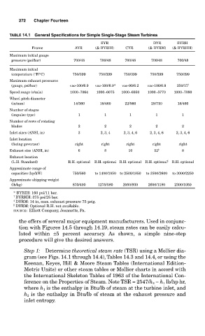
TABLE 14.1 General Specifications for Simple Single-Stage Steam Turbines
BYR DYR BYRH
Frame AYR (& BYRIH) CYR (& DYRM) (& BYRHH)
Maximum initial gauge
pressure (psi/bar) 700/48 700/48 700/48 700/48 700/48
Maximum initial
temperature (°F/°C) 750/399 750/399 750/399 750/399 750/399
Maximum exhaust pressures
(gauge, psi/bar) vac-100/6.9 vac-100/6.9* vac-90/6.2 vac-100/6.9 250/17 †
Speed range (r/min) 1000–7064 1000–6675 1000–6950 1000–5770 1000–7090
Wheel pitch diameter
(in/mm) 14/360 18/460 22/560 28/710 18/460
Number of stages
(impulse type) 1 1 1 1 1
Number of rows of rotating
blades 2 2 2 2 2
Inlet sizes (ANSI, in) 3 2, 3, 4 2, 3, 4, 6 2, 3, 4, 6 2, 3, 4, 6
Inlet location
(facing governor) right right right right right
Exhaust size (ANSI, in) 6 8 10 12 ‡ 8
Exhaust location
(L.H. Standard) R.H. optional R.H. optional R.H. optional R.H. optional § R.H. optional
Approximate range of
capacities (hp/kW) 750/560 to 1400/1050 to 2500/1850 to 3500/2600 to 3000/2250
Approximate shipping weight
(lb/kg) 870/400 1275/580 2050/930 2600/1180 2300/1050
* BYRIH: 160 psi/11 bar.
† BYRHH: 375 psi/25 bar.
‡ DYRM: 14 in, max. exhaust pressure 75 psig.
§ DYRM: Optional R.H. not available.
SOURCE: Elliott Company, Jeannette, Pa.
the offers of several major equipment manufacturers. Used in conjunc-
tion with Figures 14.5 through 14.19, steam rates can be easily calcu-
lated within ±5 percent accuracy. As shown, a simple nine-step
procedure will give the desired answers.
Step 1: Determine theoretical steam rate (TSR) using a Mollier dia-
gram (see Figs. 14.1 through 14.4), Tables 14.3 and 14.4, or using the
Keenan, Keyes, Hill & Moore Steam Tables (International Edition-
Metric Units) or other steam tables or Mollier charts in accord with
the International Skeleton Tables of 1963 of the International Con-
ference on the Properties of Steam. Note TSR = 2547/h 2 − h 1 lb/hp⋅hr,
where h 1 is the enthalpy in Btu/lb of steam at the turbine inlet, and
h 2 is the enthalpy in Btu/lb of steam at the exhaust pressure and
inlet entropy.