
Page 326 - Steam Turbines Design, Applications, and Rerating
P. 326
300 Chapter Fourteen
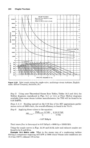
Figure 14.30 Inlet nozzle sizing for single-valve, multistage steam turbines, English
units. (Elliott Company, Jeannette, Pa.)
Step 2: Using your Theoretical Steam Rate Tables, Tables 14.3 and 14.4, the
Mollier diagrams reproduced in Figs. 14.1 or 14.2, or Polar Mollier diagrams
available from some steam turbine manufacturers, the TSR will be found to be
8.18 lb/kWh.
Steps 3, 4, 5: Reading upward on the 8.18 line of the 2E7 approximate perfor-
mance curve at 5000 r/min, the overall efficiency is found to be 70.4%.
Step 6: Applying these values to the equation:
TSR lb / kWh (0.746) 8.18 (0.746)
SR lb / hp⋅h = =
η 0.704
= 8.67 lb/hp⋅h
Total steam flow is then equal to 8.67 lb/hp⋅h × 6000 hp = 52020 lb/h.
Using the nozzle curves in Figs. 14.30 and 14.32, inlet and exhaust nozzles are
found to be 6 and 36 in.
Example 14.4: Metric units What is the steam rate of a condensing turbine
driving a compressor requiring 4475 kW at 5000 r/min? Steam inlet conditions are
41.4 bar, 340°C; exhaust 135 m bar.