
Page 52 - Steam Turbines Design, Applications, and Rerating
P. 52
Turbine Casing and Major Stationary Components 33
2.2 Steam Admission Sections
As the term implies, steam enters the turbine at the admission section
through one or more governing valves. Either bar lift or cam lift arrange-
ments are common. These are shown in Figs. 2.3 and 2.4, respectively.
The bar lift valve gear shown in Fig. 2.3 is relatively simple. A servo
motor operates the lever that raises or lowers the horizontal bar that is
enclosed in the steam chest. The governing valves hang loosely on the
bar and are adjusted for length of stem so that they will open sequen-
tially. There are typically five valves in this design but as many as
seven valves have been used.
The flow capacity of this type of design is limited to about 600,000
lb/h (273 T/H). Special precautions should be used on high-flow appli-
cations to prevent these free-hanging valves from spinning and wear-
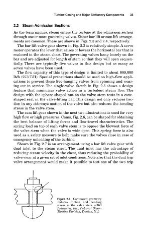
ing out in service. The single-valve sketch in Fig. 2.5 shows a design
feature that minimizes valve action in a turbulent steam flow. The
design with the sphere-shaped nut on the valve stem rests in a cone-
shaped seat in the valve-lifting bar. This design not only reduces fric-
tion in any sideways motion of the valve but also reduces the bending
stress in the valve stem.
The cam lift gear shown in the next two illustrations is used for very
high flow or high pressures. Cams, Fig. 2.6, can be shaped for obtaining
the best balance of lifting forces and flow-travel characteristics. The
spring load on top of each valve stem is to oppose the blowout force of
the valve stem when the valve is wide open. This spring force is also
used as a safety measure to help make sure the valves close in case of
emergency unloading of the turbine.
Shown in Fig. 2.7 is an arrangement using a bar lift valve gear with
dual inlet to the steam chest. The dual inlet has the advantage of
reducing steam velocity in the chest, thus reducing the probability of
valve wear at a given set of inlet conditions. Note also that the dual trip
valve arrangement would make it possible to test one of the two trip
Figure 2.5 Contoured geometry
reduces friction and bending
stress in the valve stem. (IMO
Industries, Inc., DeLaval Steam
Turbine Division, Trenton, N.J.