
Page 117 - Structural Steel Designers Handbook AISC, AASHTO, AISI, ASTM, and ASCE-07 Design Standards
P. 117
Brockenbrough_Ch03.qxd 9/29/05 5:05 PM Page 3.49
CONNECTIONS
CONNECTIONS 3.49
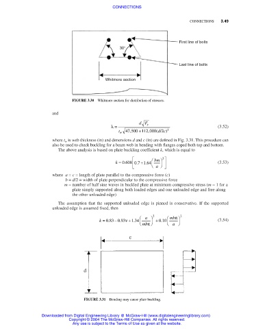
First line of bolts
30°
Last line of bolts
Whitmore section
FIGURE 3.30 Whitmore section for distribution of stresses.
and
dF y
λ= (3.52)
t w 47 500 +112 000, ( d c 2/ ) 2
,
where t w is web thickness (in) and dimensions d and c (in) are defined in Fig. 3.31. This procedure can
also be used to check buckling for a beam web in bending with flanges coped both top and bottom.
The above analysis is based on plate buckling coefficient k, which is equal to
bm 2
.
+ .
.
k = 0 608 07 164 (3.53)
a
where a = c = length of plate parallel to the compressive force (c)
b = d/2 = width of plate perpendicular to the compressive force
m = number of half sine waves in buckled plate at minimum compressive stress (m = 1 for a
plate simply supported along both loaded edges and one unloaded edge and free along
the other unloaded edge)
The assumption that the supported unloaded edge is pinned is conservative. If the supported
unloaded edge is assumed fixed, then
π
k = 083 093ν +134 a 2 + 010 mb 2 (3.54)
.
− .
.
.
mb a
π
FIGURE 3.31 Bending may cause plate buckling.
Downloaded from Digital Engineering Library @ McGraw-Hill (www.digitalengineeringlibrary.com)
Copyright © 2004 The McGraw-Hill Companies. All rights reserved.
Any use is subject to the Terms of Use as given at the website.