
Page 145 - Structural Steel Designers Handbook AISC, AASHTO, AISI, ASTM, and ASCE-07 Design Standards
P. 145
Brockenbrough_Ch03.qxd 9/29/05 5:05 PM Page 3.77
CONNECTIONS
CONNECTIONS 3.77
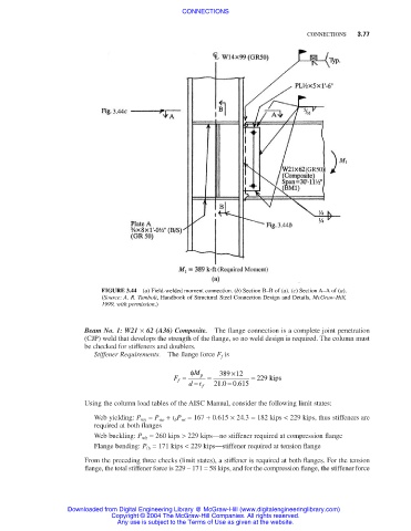
FIGURE 3.44 (a) Field-welded moment connection. (b) Section B–B of (a). (c) Section A–A of (a).
(Source: A. R. Tamboli, Handbook of Structural Steel Connection Design and Details, McGraw-Hill,
1999, with permission.)
Beam No. 1: W21 × 62 (A36) Composite. The flange connection is a complete joint penetration
(CJP) weld that develops the strength of the flange, so no weld design is required. The column must
be checked for stiffeners and doublers.
Stiffener Requirements. The flange force F f is
φ M 389 ×12
F = p = = 229 kips
−
f
dt f 21.0 − 0 615
.
Using the column load tables of the AISC Manual, consider the following limit states:
Web yielding: P wy = P wo + t b P wi = 167 + 0.615 × 24.3 = 182 kips < 229 kips, thus stiffeners are
required at both flanges
Web buckling: P wb = 260 kips > 229 kips—no stiffener required at compression flange
Flange bending: P fb = 171 kips < 229 kips—stiffener required at tension flange
From the preceding three checks (limit states), a stiffener is required at both flanges. For the tension
flange, the total stiffener force is 229 – 171 = 58 kips, and for the compression flange, the stiffener force
Downloaded from Digital Engineering Library @ McGraw-Hill (www.digitalengineeringlibrary.com)
Copyright © 2004 The McGraw-Hill Companies. All rights reserved.
Any use is subject to the Terms of Use as given at the website.