
Page 150 - Structural Steel Designers Handbook AISC, AASHTO, AISI, ASTM, and ASCE-07 Design Standards
P. 150
Brockenbrough_Ch03.qxd 9/29/05 5:05 PM Page 3.82
CONNECTIONS
3.82 CHAPTER THREE
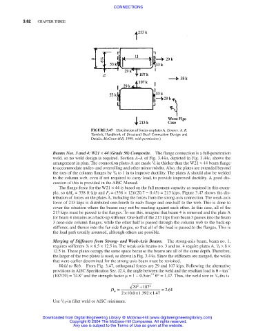
FIGURE 3.47 Distribution of forces on plates A. (Source: A. R.
Tamboli, Handbook of Structural Steel Connection Design and
Details, McGraw-Hill, 1999, with permission.)
Beams Nos. 3 and 4: W21 × 44 (Grade 50) Composite. The flange connection is a full-penetration
weld, so no weld design is required. Section A–A of Fig. 3.44a, depicted in Fig. 3.44c, shows the
1
arrangement in plan. The connection plates A are made / 4 in thicker than the W21 × 44 beam flange
to accommodate under- and overrolling and other minor misfits. Also, the plates are extended beyond
3
the toes of the column flanges by / 4 to 1 in to improve ductility. The plates A should also be welded
to the column web, even if not required to carry load, to provide improved ductility. A good dis-
cussion of this is provided in the AISC Manual.
The flange force for the W21 × 44 is based on the full moment capacity as required in this exam-
ple, so φM p = 358 ft⋅kip and F f = (358 × 12)/(20.7 − 0.45) = 213 kips. Figure 3.47 shows the dis-
tribution of forces on the plates A, including the forces from the strong-axis connection. The weak-axis
force of 213 kips is distributed one-fourth to each flange and one-half to the web. This is done to
cover the situation where the beams may not be reacting against each other. In this case, all of the
213 kips must be passed to the flanges. To see this, imagine that beam 4 is removed and the plate A
for beam 4 remains as a back-up stiffener. One-half of the 213 kips from beam 3 passes into the beam
3 near-side column flanges, while the other half is passed through the column web to the back-up
stiffener, and thence into the far-side flanges, so that all of the load is passed to the flanges. This is
the load path usually assumed, although others are possible.
Merging of Stiffeners from Strong- and Weak-Axis Beams. The strong-axis beam, beam no. 1,
requires stiffeners / 2 × 6.5 × 12.5 in. The weak-axis beams no. 3 and no. 4 require plates A, / 4 × 8 ×
3
1
12.5 in. These plates occupy the same space because the beams are all of the same depth. Therefore,
the larger of the two plates is used, as shown in Fig. 3.44a. Since the stiffeners are merged, the welds
that were earlier determined for the strong-axis beam must be revisited.
Weld to Web. From Fig. 3.47, orthogonal forces are 29 and 107 kips. Following the alternative
provisions in AISC Specification Sec. J2.4, the angle between the weld and the resultant load is θ= tan −1
1
(107/29) = 74.8° and the strength factor µ= 1 + 0.5sin 1.5 θ° = 1.47. Thus, the weld size in / 16ths is
D = 29 2 +107 2 = 261
.
w
.
.
2 ×100 . ×1392 ×147
3
Use / 16-in fillet weld or AISC minimum.
Downloaded from Digital Engineering Library @ McGraw-Hill (www.digitalengineeringlibrary.com)
Copyright © 2004 The McGraw-Hill Companies. All rights reserved.
Any use is subject to the Terms of Use as given at the website.