
Page 203 - Structural Steel Designers Handbook AISC, AASHTO, AISI, ASTM, and ASCE-07 Design Standards
P. 203
Brockenbrough_Ch04.qxd 9/29/05 5:09 PM Page 4.31
BUILDING CODES, LOADS, AND FIRE PROTECTION*
BUILDING CODES, LOADS, AND FIRE PROTECTION 4.31
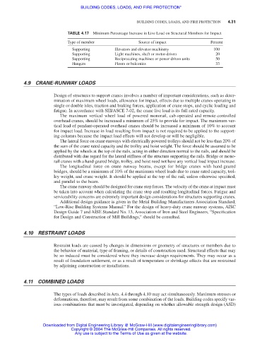
TABLE 4.17 Minimum Percentage Increase in Live Load on Structural Members for Impact
Type of member Source of impact Percent
Supporting Elevators and elevator machinery 100
Supporting Light machines, shaft or motor-driven 20
Supporting Reciprocating machines or power-driven units 50
Hangers Floors or balconies 33
4.9 CRANE-RUNWAY LOADS
Design of structures to support cranes involves a number of important considerations, such as deter-
mination of maximum wheel loads, allowance for impact, effects due to multiple cranes operating in
single or double isles, traction and braking forces, application of crane stops, and cyclic loading and
fatigue. In accordance with SEI/ASCE 7-02, the crane live load is its full rated capacity.
The maximum vertical wheel load of powered monorail, cab-operated and remote-controlled
overhead cranes, should be increased a minimum of 25% to provide for impact. The maximum ver-
tical load of pendant-operated overhead cranes should be increased a minimum of 10% to account
for impact load. Increase in load resulting from impact is not required to be applied to the support-
ing columns because the impact load effects will not develop or will be negligible.
The lateral force on crane runways with electrically powered trolleys should not be less than 20% of
the sum of the crane rated capacity and the trolley and hoist weight. The force should be assumed to be
applied by the wheels at the top of the rails, acting in either direction normal to the rails, and should be
distributed with due regard for the lateral stiffness of the structure supporting the rails. Bridge or mono-
rail cranes with a hand-geared bridge, trolley, and hoist need not have any vertical load impact increase.
The longitudinal force on crane runway beams, except for bridge cranes with hand-geared
bridges, should be a minimum of 10% of the maximum wheel loads due to crane rated capacity, trol-
ley weight, and crane weight. It should be applied at the top of the rail, unless otherwise specified,
and parallel to the beam.
The crane runway should be designed for crane stop forces. The velocity of the crane at impact must
be taken into account when calculating the crane stop and resulting longitudinal forces. Fatigue and
serviceability concerns are extremely important design considerations for structures supporting cranes.
Additional design guidance is given in the Metal Building Manufacturers Association Standard,
“Low-Rise Building Systems Manual.” For the design of heavy-duty crane runway systems, AISC
Design Guide 7 and AISE Standard No. 13, Association of Iron and Steel Engineers, “Specification
for Design and Construction of Mill Buildings,” should be consulted.
4.10 RESTRAINT LOADS
Restraint loads are caused by changes in dimensions or geometry of structures or members due to
the behavior of material, type of framing, or details of construction used. Structural effects that may
be so induced must be considered where they increase design requirements. They may occur as a
result of foundation settlement, or as a result of temperature or shrinkage effects that are restrained
by adjoining construction or installations.
4.11 COMBINED LOADS
The types of loads described in Arts. 4.4 through 4.10 may act simultaneously. Maximum stresses or
deformations, therefore, may result from some combination of the loads. Building codes specify var-
ious combinations that must be investigated, depending on whether allowable strength design (ASD)
Downloaded from Digital Engineering Library @ McGraw-Hill (www.digitalengineeringlibrary.com)
Copyright © 2004 The McGraw-Hill Companies. All rights reserved.
Any use is subject to the Terms of Use as given at the website.