
Page 230 - Structural Steel Designers Handbook AISC, AASHTO, AISI, ASTM, and ASCE-07 Design Standards
P. 230
Brockenbrough_Ch05.qxd 9/29/05 5:12 PM Page 5.10
CRITERIA FOR BUILDING DESIGN
5.10 CHAPTER FIVE
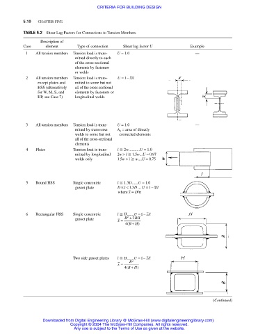
TABLE 5.2 Shear Lag Factors for Connections to Tension Members
Description of
Case element Type of connection Shear lag factor U Example
1 All tension members Tension load is trans- U = 1.0 —
mitted directly to each
of the cross-sectional
elements by fasteners
or welds
1
2 All tension members Tension load is trans- U =− x l /
except plates and mitted to some but not
HSS (alternatively all of the cross-sectional
for W, M, S, and elements by fasteners or
HP, see Case 7) longitudinal welds
3 All tension members Tension load is trans- U = 1.0 —
mitted by transverse A n = area of directly
welds to some but not connected elements
all of the cross-sectional
elements
4 Plates Tension load is trans- l 2w...........U = 1.0
mitted by longitudinal 2w > l 1.5w...U = 0.87
welds only 1.5w > l w....U = 0.75
5 Round HSS Single concentric l 1.3D......U = 1.0
D
gusset plate Dl≤<13 … U = − x l /
.
1
where x = D/π
/
6 Rectangular HSS Single concentric l H.......U =−1 x l
2
gusset plate x = B + 2 BH
+
4( BH)
Two side gusset plates l H.......U =−1 x l /
2
x = B
+
4( BH)
(Continued)
Downloaded from Digital Engineering Library @ McGraw-Hill (www.digitalengineeringlibrary.com)
Copyright © 2004 The McGraw-Hill Companies. All rights reserved.
Any use is subject to the Terms of Use as given at the website.