
Page 233 - Structural Steel Designers Handbook AISC, AASHTO, AISI, ASTM, and ASCE-07 Design Standards
P. 233
Brockenbrough_Ch05.qxd 9/29/05 5:12 PM Page 5.13
CRITERIA FOR BUILDING DESIGN
CRITERIA FOR BUILDING DESIGN 5.13
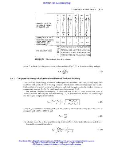
FIGURE 5.1 Effective length factor K for columns.
where F e = elastic buckling stress determined according to Eq. (5.22) or from the stability analysis:
π 2 E
F = (5.22)
e
( KL r / ) 2
5.4.2 Compressive Strength for Torsional and Flexural-Torsional Buckling
This article applies to singly symmetric and unsymmetric members, and certain doubly symmetric
members, such as cruciform or built-up columns. The elements of the members must have width–
thickness ratios for axially compressed elements such that the sections are classified as compact or
noncompact (see Art. 5.1.5). For single-angle members, see Art. 5.4.3.
The nominal compressive strength P n is calculated from Eq. (5.19) based on the limit states of
flexural-torsional buckling and torsional buckling. F cr is determined as follows: For double-angle
and tee-shaped compression members,
F + F 4 FF H
F = cry 2 H crz 1 − 1 − ( F cry cry crz 2 (5.23)
+
cr
F )
crz
where F cry is determined according to Eq. (5.20) or (5.21) for flexural buckling about the y axis of
symmetry with (KL/r) = (KL/r y ), and
F crz = GJ (5.24)
Ar 2
o
For all other cases, F cr is determined from Eq. (5.20) or (5.21), but with F e determined as follows:
For doubly symmetric members,
π 2 EC 1
F = w + GJ (5.25)
e
( KL) 2 I + I y
x
z
Downloaded from Digital Engineering Library @ McGraw-Hill (www.digitalengineeringlibrary.com)
Copyright © 2004 The McGraw-Hill Companies. All rights reserved.
Any use is subject to the Terms of Use as given at the website.