
Page 265 - Structural Steel Designers Handbook AISC, AASHTO, AISI, ASTM, and ASCE-07 Design Standards
P. 265
Brockenbrough_Ch05.qxd 9/29/05 5:12 PM Page 5.45
CRITERIA FOR BUILDING DESIGN
CRITERIA FOR BUILDING DESIGN 5.45
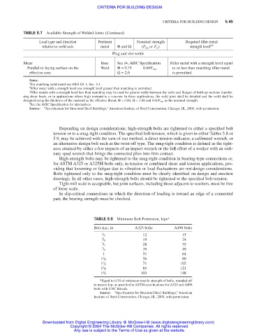
TABLE 5.7 Available Strength of Welded Joints (Continued)
Load type and direction Pertinent Nominal strength Required filler metal
relative to weld axis metal Φ and Ω (F bm or F w ) strength level a,b
Plug and slot welds
Shear Base See J4, AISC Specification Filler metal with a strength level equal
Parallel to faying surface on the Weld Φ= 0.75 0.60F Exx to or less than matching filler metal
effective area Ω= 2.0 is permitted.
Notes:
a
For matching weld metal see AWS D1.1, Sec. 3.3.
b
Filler metal with a strength level one strength level greater than matching is permitted.
c
Filler metals with a strength level less than matching may be used for groove welds between the webs and flanges of built-up sections transfer-
ring shear loads, or in applications where high restraint is a concern. In these applications, the weld joint shall be detailed and the weld shall be
designed using the thickness of the material as the effective throat, Φ= 0.80, Ω= 1.88 and 0.60F Exx as the nominal strength.
d
See the AISC Specification for alternatives.
Source: “Specification for Structural Steel Buildings,” American Institute of Steel Construction, Chicago, Ill., 2005, with permission.
Depending on design considerations, high-strength bolts are tightened to either a specified bolt
tension or to a snug-tight condition. The specified bolt tension, which is given in either Tables 5.8 or
5.9, may be achieved with the turn-of-nut method, a direct tension indicator, a calibrated wrench, or
an alternative design bolt such as the twist-off type. The snug-tight condition is defined as the tight-
ness attained by either a few impacts of an impact wrench or the full effort of a worker with an ordi-
nary spud wrench that brings the connected plies into firm contact.
High-strength bolts may be tightened to the snug-tight condition in bearing-type connections or,
for ASTM A325 or A325M bolts only, in tension or combined shear and tension applications, pro-
viding that loosening or fatigue due to vibration or load fluctuations are not design considerations.
Bolts tightened only to the snug-tight condition must be clearly identified on design and erection
drawings. In all other cases, high-strength bolts should be tightened to the specified bolt tension.
Tight mill scale is acceptable, but joint surfaces, including those adjacent to washers, must be free
of loose scale.
In slip-critical connections in which the direction of loading is toward an edge of a connected
part, the bearing strength must be checked.
TABLE 5.8 Minimum Bolt Pretension, kips*
Bolt size, in A325 bolts A490 bolts
1 12 15
/ 2
5 19 24
/ 8
3 28 35
/ 4
7 39 49
/ 8
1 51 64
1
1 / 8 56 80
1 71 102
1 / 4
3
1 / 8 85 121
1 103 148
1 / 2
*Equal to 0.70 of minimum tensile strength of bolts, rounded off
to nearest kip, as specified in ASTM specifications for A325 and A490
bolts with UNC threads.
Source: “Specification for Structural Steel Buildings,” American
Institute of Steel Construction, Chicago, Ill., 2005, with permission.
Downloaded from Digital Engineering Library @ McGraw-Hill (www.digitalengineeringlibrary.com)
Copyright © 2004 The McGraw-Hill Companies. All rights reserved.
Any use is subject to the Terms of Use as given at the website.