
Page 318 - Structural Steel Designers Handbook AISC, AASHTO, AISI, ASTM, and ASCE-07 Design Standards
P. 318
Brockenbrough_Ch07.qxd 9/29/05 5:16 PM Page 7.2
FLOOR AND ROOF SYSTEMS
7.2 CHAPTER SEVEN
TABLE 7.1 Equivalent Thicknesses for required. For example, a maximum beam spacing of about
Cold-Formed Steel 15 ft can be achieved with 3-in deck. However, each project
must be evaluated on an individual basis to determine the
Gage designation Design thickness, in most efficient combination of deck depth and beam spacing.
28 0.0149 For special long-span applications, metal deck is avail-
1
1
26 0.0179 able with depths of 4 / 2, 6, and 7 / 2 in from some manu-
24 0.0239 facturers.
22 0.0299
20 0.0359 Composite versus Noncomposite Construction. Ordinarily,
18 0.0478 composite metal-deck construction is used with structural-
16 0.0598
steel framing. In this case, the deck acts not only as a per-
manent form for the concrete slab but also, after the
concrete hardens, as the positive bending reinforcement for the slab. To achieve this composite
action, deformations are formed in the deck to provide a mechanical interlock with the concrete
(Fig. 7.1). Although not serving a primary structural purpose, welded wire fabric is usually placed
within the concrete slab about 1 in below the top surface to minimize cracking due to concrete
shrinkage and thermal effects. This welded wire fabric also provides, to a limited degree, some
amount of crack control in negative-moment regions of the slab over supporting members.
In cases where the long-term reliability of composite metal deck will be questionable, the metal
deck should be used solely as a form, and reinforcement should be placed within the slab to resist
all design loadings. For example, in regions where deicing chemicals are applied to streets, metal
deck used in parking structures is susceptible to corrosion and may eventually be ineffective unless
special precautions are taken.
Noncomposite metal deck is used solely as a form to support the concrete until it hardens.
Reinforcement should be placed within the slab to resist all design loadings.
Noncellular versus Cellular Deck. Though relatively uncommon in today’s steel-framed con-
struction, it is possible to distribute a building’s electrical wiring within the floor deck system, in
which case cellular metal deck can be used in lieu of noncellular deck. However, in cases where floor
depth is not critical, maximum wiring flexibility and capacity can be attained by using a raised access
floor above the structural floor deck.
Cellular deck is essentially noncellular deck, such as that shown in Fig. 7.1, with a flat sheet
added to the bottom of the deck to create cells (Fig. 7.2). Electrical, power, and telephone wiring is
placed within the cells for distribution over the entire floor area. In many cases, a sufficient number
of cells is obtained by combining alternate panels of cellular deck and noncellular deck, which is
called a blended system (Fig. 7.3). When cellular deck is used, the 3-in depth is the minimum pre-
1
ferred because it provides convenient space for wiring. The 1 / 2-in depth is rarely used.
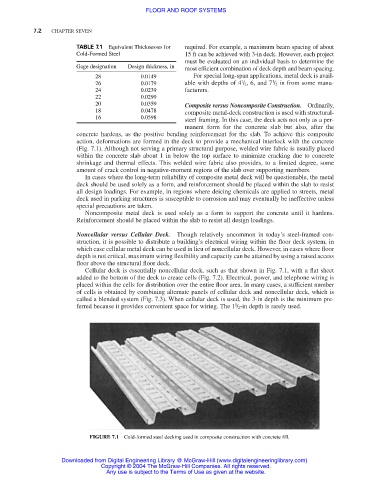
FIGURE 7.1 Cold-formed steel decking used in composite construction with concrete fill.
Downloaded from Digital Engineering Library @ McGraw-Hill (www.digitalengineeringlibrary.com)
Copyright © 2004 The McGraw-Hill Companies. All rights reserved.
Any use is subject to the Terms of Use as given at the website.