
Page 378 - Structural Steel Designers Handbook AISC, AASHTO, AISI, ASTM, and ASCE-07 Design Standards
P. 378
Brockenbrough_Ch08.qxd 9/29/05 5:21 PM Page 8.32
LATERAL-FORCE DESIGN
8.32 CHAPTER EIGHT
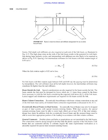
FIGURE 8.15 Typical connection details and stiffener arrangement for an eccentric
braced frame.
frames. Full-depth web stiffeners are also required at each end of the link beam, as illustrated in
Fig. 8.15. The high shear stress in the web of the link beam results in the potential for web buck-
ling during large inelastic cycles, and intermediate web stiffeners are also likely to be required as
shown in Fig. 8.15. Spacing s for intermediate stiffeners for link beams with link rotation angle of
0.08 rad is
s = 30 t − d (8.33a)
w
5
When the link rotation angle is 0.02 rad or less,
s = 52 t − d (8.33b)
w
5
For link beams with link rotation angle between 0.02 and 0.08 rad, the spacing must be determined
by interpolation. The web stiffeners must all be full depth; however, the intermediate stiffeners may
sometimes be lighter than the end stiffeners.
Beam Outside the Link. Special considerations are also required for the beam outside the link. The
beam outside the link must be designed for forces which are 1.1 times those caused by the brace
force necessary to yield the link beam considering the expected yield stress (R y F y ) of the link beam.
Lateral support and slenderness requirements are required for the beam outside the link.
Beam–Column Connections. Eccentrically braced frames with beam–column connections at one end
of the link beam must satisfy all moment-frame connection requirements as discussed in Art. 8.7.1.
Eccentrically Braced Frames in Dual Systems. Eccentrically braced frames may also be designed
as part of dual systems with special moment-resisting frames. With dual systems, the special
moment-resisting frame must be able to resist loads which are at least 25% of the total seismic-
design base shear. In addition, both the eccentrically braced frame and the moment frame must be
able to resist their appropriate portion of the loading in accordance with their relative stiffness.
General Comments. Doubler plates and holes or penetrations are not permitted in the link beams.
The connections must be strong enough to develop fully the plastic capacity of the link beams. Link
beams that are connected directly to columns require the same experimental verification as is
presently required for special steel moment-resisting frames.
Downloaded from Digital Engineering Library @ McGraw-Hill (www.digitalengineeringlibrary.com)
Copyright © 2004 The McGraw-Hill Companies. All rights reserved.
Any use is subject to the Terms of Use as given at the website.