Page 382 - Structural Steel Designers Handbook AISC, AASHTO, AISI, ASTM, and ASCE-07 Design Standards
P. 382

Brockenbrough_Ch08.qxd  9/29/05  5:21 PM  Page 8.36


                                                    LATERAL-FORCE DESIGN


                   8.36  CHAPTER EIGHT

                               the frame. The frame has two interior columns. So one-third of the shear in each story is distributed
                               to the interior columns and half of this, or one-sixth, is distributed to the exterior columns (Fig. 8.17).
                               The other member forces are computed by equations of equilibrium on each subassemblage. For
                               example, for the subassemblage at the top of the frame in Fig. 8.17, setting the sum of the moments
                               equal to zero yields

                                                      l       h                h
                                                           417
                                                                           417
                                                        S = .      or   S = .                      (8.34)
                                                        1
                                                                         1
                                                      2       2                l
                               Setting the sum of the vertical forces equal to zero gives
                                                            A =− S =− 417  h                       (8.35)
                                                                      .
                                                             4
                                                                  1
                                                                         l
                               Setting the sum of the horizontal forces equal to zero results in
                                                           A =  25 417 =  2083                     (8.36)
                                                                 −
                                                                         .
                                                                   .
                                                            1
                               For the central top subassemblage:
                                              l           h             h              h
                                                                          833 417)−
                                                S (  1  +  S ) =  833  or  S =  ( .  .  =  416     (8.37)
                                                        .
                                                                                     .
                                                                     2
                                                    2
                                              2           2             l               l
                               The remaining axial and shear forces can be determined by this procedure, and bending moments
                               can be determined directly from these forces from equilibrium equations.
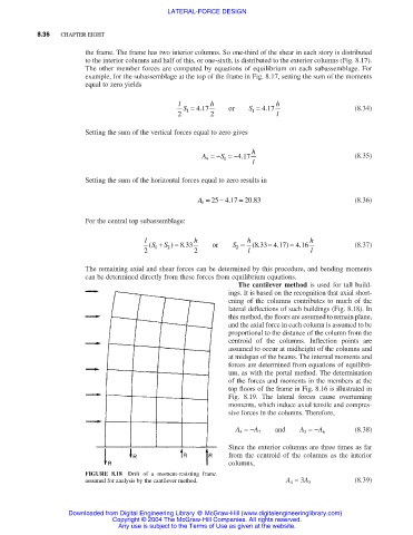
                                                                     The cantilever method is used for tall build-
                                                                   ings. It is based on the recognition that axial short-
                                                                   ening of the columns contributes to much of the
                                                                   lateral deflections of such buildings (Fig. 8.18). In
                                                                   this method, the floors are assumed to remain plane,
                                                                   and the axial force in each column is assumed to be
                                                                   proportional to the distance of the column from the
                                                                   centroid of the columns. Inflection points are
                                                                   assumed to occur at midheight of the columns and
                                                                   at midspan of the beams. The internal moments and
                                                                   forces are determined from equations of equilibri-
                                                                   um, as with the portal method. The determination
                                                                   of the forces and moments in the members at the
                                                                   top floors of the frame in Fig. 8.16 is illustrated in
                                                                   Fig. 8.19.  The lateral forces cause overturning
                                                                   moments, which induce axial tensile and compres-
                                                                   sive forces in the columns. Therefore,
                                                                               and                 (8.38)
                                                                     A 4 =−A 7       A 5 =−A 6
                                                                   Since the exterior columns are three times as far
                                                                   from the centroid of the columns as the interior
                                                                   columns,
                               FIGURE 8.18  Drift of a moment-resisting frame
                               assumed for analysis by the cantilever method.    A 4 = 3A 5        (8.39)


                           Downloaded from Digital Engineering Library @ McGraw-Hill (www.digitalengineeringlibrary.com)
                                      Copyright © 2004 The McGraw-Hill Companies. All rights reserved.
                                       Any use is subject to the Terms of Use as given at the website.
   377   378   379   380   381   382   383   384   385   386   387