
Page 64 - Structural Steel Designers Handbook AISC, AASHTO, AISI, ASTM, and ASCE-07 Design Standards
P. 64
Brockenbrough_Ch02.qxd 9/29/05 5:01 PM Page 2.26
FABRICATION AND ERECTION*
2.26 CHAPTER TWO
2.13 ERECTION PROCEDURE FOR BRIDGES
Bridges are erected by a variety of methods. The choice of method in a particular case is influenced
by type of structure, length of span, site conditions, manner in which material is delivered to the site,
and equipment available. Bridges over navigable waterways are sometimes limited to erection pro-
cedures that will not inhibit traffic flow; for example, falsework may be prohibited.
Regardless of erection procedure selected, there are two considerations that override all others.
The first is the security and stability of the structure under all conditions of partial construction,
construction loading, and wind loading that will be encountered during erection. The second consider-
ation is that the bridge must be erected in such a manner that it will perform as intended. For example,
in continuous structures, this can mean that jacks must be used on the structure to effect the proper
stress distribution. These considerations will be elaborated upon later as they relate to erection of
particular types of bridges.
Simple-beam bridges are often erected with a crawler or truck crane. Bridges of this type
generally require a minimal amount of engineering and are put up routinely by an experienced
erector. One problem that does occur with beam spans, however, and especially composite beam
spans, arises from lateral instability of the top flange during lifting or before placement of perma-
nent bracing. Beams or girders that are too limber to lift unbraced require temporary compression-
flange support, often in the form of a stiffening truss. Lateral support also may be provided by
assembling two adjacent members on the ground with their bracing or cross members and erecting
the assembly in one piece. Beams that can be lifted unbraced but are too limber to span alone also
can be handled in pairs. It may be necessary to hold them with the crane until bracing connections can
be made.
Continuous-beam bridges are erected in much the same way as simple-beam bridges. One or
more field splices, however, will be present in the stringers of continuous beams. With bolted field
splices, the holes in the members and connection material have been reamed in the shop to insure
proper alignment of the member. With a welded field splice, it is generally necessary to provide
temporary connection material to support the member and permit adjustment for alignment and
proper positioning for welding. For economy, field splices should be located at points of relatively
low bending moment. It is also economical to allow the erector some options regarding splice
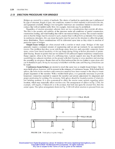
location, which may materially affect erection cost. The arrangement of splices in Fig. 2.10a, for
example, will require, if falsework is to be avoided, that both end spans be erected first, then the
center spans. The splice arrangement shown in Fig. 2.10b will allow erection to proceed from one
FIGURE 2.10 Field splices in girder bridges.
Downloaded from Digital Engineering Library @ McGraw-Hill (www.digitalengineeringlibrary.com)
Copyright © 2004 The McGraw-Hill Companies. All rights reserved.
Any use is subject to the Terms of Use as given at the website.