
Page 111 - Structural Steel Designers Handbook AISC, AASHTO, AISI, ASTM, and ASCE-07 Design Standards
P. 111
Brockenbrough_Ch03.qxd 9/29/05 5:05 PM Page 3.43
CONNECTIONS
CONNECTIONS 3.43
The design strength for bolts 1 and 2 is 20.2 kips, based on bolt tear-out through the edge of the plate,
and the design strength for bolts 3 and 4 is 14.7 kips, based on bolt tear-out through the edge of the
strut web. Therefore, the design strength of the connection is (2)14.7 + (2)20.2 = 69.8 kips.
It is possible to avoid the complications presented above involving bolt tear-out by increasing the
edge distances and spacings such that bearing controls. To do this requires that
1.2F u L c t ≥ 2.4F u d b t (3.30)
Thus,
(3.31)
L c ≥ 2d b
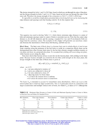
This equation was used to develop Table 3.11, which shows minimum edge distances to center of
hole and minimum spacings center to center of holes to preclude tear-out. Note that the center edge
1
distance L e for all bolt diameters and the spacing s required for 1-in- and 1 / 8-in-diameter bolts are
larger than the customary values. The examples in this chapter will generally use customary values
and illustrate the interrelation of bolt shear, bolt bearing, and bolt tear-out.
Block Shear. The limit state of block shear is a fracture limit state in which a block of steel is torn
from a member along the perimeter of the bolt holes or welds in a connection. Block shear can be
distinguished from other fracture limit states by the fact that ultimate strength mobilizes tension on
one plane and shear on a perpendicular plane. It is assumed that yielding will occur along one plane,
while fracture occurs along the other.
Tests have shown that fracture always occurs first on the tension plane, with yielding on the shear
plane. Because fracture strength can sometimes be less than yield strength on the shear plane, the
design strength for the limit state of block shear is given as
φR n =φ[U bs F u A nt + min(0.6F y A gv , 0.6F u A nv )] (3.32)
where φ= 0.75
A nt = net area subjected to tension, in 2
A gv = gross area subjected to shear, in 2
A nv = net area subjected to shear, in 2
U bs = shear lag factor for block shear
= 1.0 where the tension stress is uniform
= 0.5 where the tension stress is nonuniform
The factor U bs is intended to account for nonuniform stress distributions, which can occur at the
tension plane due to relatively large eccentricities. This is of particular concern at connections with
larger eccentricities and multiple vertical rows of bolts, for which U bs is taken as 0.5. Although the
TABLE 3.11 Minimum Edge Distance to Center of Hole and Minimum Spacing Center to Center of Holes
to Preclude Tear-out Failure for Standard Holes
Bolt diameter, Clear edge distance Hole diameter Center edge distance a Center-to-center
d, in L c , in d h , in L e , in spacing s, in
3 1 13 2 3 b
/ 4 1 / 2 / 16
7 3 15 1 3 b
/ 8 1 / 4 / 16 2 / 4
1 c
1
5
1 2 1 / 16 2 / 8 3 / 2
1 1 3 7 1 c
1 / 8 2 / 4 1 / 16 2 / 8 3 / 2
a 1
Rounded up to nearest / 8 in.
b
Rounded up to customary pitch of 3 in.
c 1
Rounded up to nearest / 2 in.
Downloaded from Digital Engineering Library @ McGraw-Hill (www.digitalengineeringlibrary.com)
Copyright © 2004 The McGraw-Hill Companies. All rights reserved.
Any use is subject to the Terms of Use as given at the website.