Page 116 - Structural Steel Designers Handbook AISC, AASHTO, AISI, ASTM, and ASCE-07 Design Standards
P. 116

Brockenbrough_Ch03.qxd  9/29/05  5:05 PM  Page 3.48


                                                        CONNECTIONS


                   3.48  CHAPTER THREE


                                                                         L
                                            L


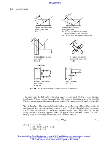
                                           Single brace to gusset   Double brace to gusset
                                           along beam span          along beam span
                                           K = 1.2                  K = 0.65 with one brace in tension
                                                                       and one brace in compression
                                                                    K = 1.2 with both braces in compression
                                        L
                                                                               L


                                          Brace at beam-column              X-bracing intersection
                                          connection                        (brace with kicker sim.)
                                          K = 0.5                           K = 2.0

                                                     L


                                                                                 L


                                          Flange plate moment           Strut connection
                                          connection                    K = 1.2
                                          K = 0.65
                                      FIGURE 3.29  K factors and buckling lengths for plates in compression.


                                 In many cases, the full width of the plate cannot be considered effective to resist buckling.
                               Therefore, the Whitmore section illustrated in Fig. 3.30 is taken as the effective width of the plate. The
                               Whitmore section is assumed to extend along the length of the connection at a 30° angle to either side.

                               Plates in Bending.  The strength of plates in bending can also be governed by buckling. Again, the
                               boundary conditions are important in determining behavior. Typically, plates in bending are assumed
                               to be free along one unloaded edge and simply supported along the other. The loaded edges are both
                               usually assumed to be simply supported. This is the approach used in the AISC Manual. The critical
                               buckling strength in bending is defined (Muir and Thornton, 2004) as


                                                              φF cr = 0.9F y Q                     (3.51)
                               where Q = 1 for λ≤ 0.7
                                      = 1.34 – 0.486λ for 0.7 <λ≤ 1.41
                                            2
                                      = 1.30/λ for λ> 1.41

                           Downloaded from Digital Engineering Library @ McGraw-Hill (www.digitalengineeringlibrary.com)
                                      Copyright © 2004 The McGraw-Hill Companies. All rights reserved.
                                       Any use is subject to the Terms of Use as given at the website.
   111   112   113   114   115   116   117   118   119   120   121