
Page 120 - Structural Steel Designers Handbook AISC, AASHTO, AISI, ASTM, and ASCE-07 Design Standards
P. 120
Brockenbrough_Ch03.qxd 9/29/05 5:05 PM Page 3.52
CONNECTIONS
3.52 CHAPTER THREE
Follow procedure in AISC Manual
Area of remaining tee = 6.2 in 2
Center of gravity of remaining tee = 4.52 in above bottom of beam
Moment of inertia of remaining tee = 133 in 4
Section modulus at top of tee = 13.8 in 3
Section modulus at bottom of tee = 29.4 in 3
M u = R u e = 80 × (5.75 + 0.375) = 490 in⋅kips
φM n =φF u S net = 0.75 × 65 × 13.8 = 673 in⋅kips ≥ 490 in⋅kips OK
Design strength for web buckling in net section of single cope:
Follow procedure in AISC Manual
c = cope length = 5.75 in; d = beam depth = 15.9 in; h o = net depth = 14.1 in
c/d = 0.362 ≤ 1; therefore, adjustment factor is f = 2(c/d) = 0.723
c/h o = 0.408 ≤ 1; therefore, plate buckling coefficient is k = 2.2(h o /c) 1.65 = 9.66
,
φF = 23 590 ( t w 2 fk )
cr
h o
.
0 275
φF = 23 ,590 ( 14 1 . ) 2 × 0.723 × 9.66 = 64.8 ksi < 0.9F y = 45 ksi
cr
φM n =φF cr S net = 45 × 13.8 = 621 in⋅kips ≥ 490 in⋅kips OK
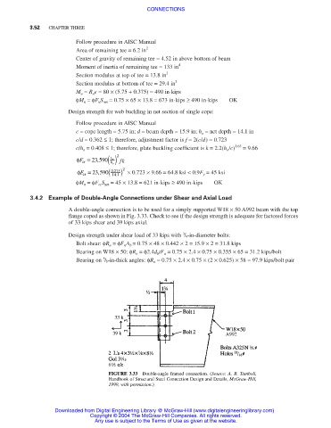
3.4.2 Example of Double-Angle Connections under Shear and Axial Load
A double-angle connection is to be used for a simply supported W18 × 50 A992 beam with the top
flange coped as shown in Fig. 3.33. Check to see if the design strength is adequate for factored forces
of 33 kips shear and 39 kips axial.
3
Design strength under shear load of 33 kips with / 4-in-diameter bolts:
Bolt shear: φR n =φF n A b = 0.75 × 48 × 0.442 × 2 = 15.9 × 2 = 31.8 kips
Bearing on W18 × 50: φR n =φ2.4d b tF u = 0.75 × 2.4 × 0.75 × 0.355 × 65 = 31.2 kips/bolt
5
Bearing on / 8-in-thick angles: φR n = 0.75 × 2.4 × 0.75 × (2 × 0.625) × 58 = 97.9 kips/bolt pair
FIGURE 3.33 Double-angle framed connection. (Source: A. R. Tamboli,
Handbook of Structural Steel Connection Design and Details, McGraw-Hill,
1999, with permission.)
Downloaded from Digital Engineering Library @ McGraw-Hill (www.digitalengineeringlibrary.com)
Copyright © 2004 The McGraw-Hill Companies. All rights reserved.
Any use is subject to the Terms of Use as given at the website.