
Page 118 - Structural Steel Designers Handbook AISC, AASHTO, AISI, ASTM, and ASCE-07 Design Standards
P. 118
Brockenbrough_Ch03.qxd 9/29/05 5:05 PM Page 3.50
CONNECTIONS
3.50 CHAPTER THREE
Taking the derivative with respect to m and setting the result equal to zero gives
a
m = 0 609. (3.55)
b
If m was a continuous function, Eq. (3.55) could be used to calculate k and then used to find the buck-
ling capacity of the plate. However, since m must be an integer, Eq. (3.55) provides only an approx-
imation. However, for any relationship of plate width to depth, the approximate value of m can be
calculated by Eq. (3.55), rounded to the nearest integer, and used to determine k. Then the next high-
est integer can be chosen for m and k recalculated. The lower k value from these two calculations is
the correct value from which to calculate the buckling capacity.
Using the more general form of the equation, λ can be calculated for the condition of fixed sup-
ported unloaded edges as
λ= 1 F y d (3.56)
167 k 2t w
This is a less conservative alternative to Eq. (3.52).
3.4 SHEAR AND AXIAL BEAM END CONNECTIONS
3.4.1 Example of Shear End-Plate Connection
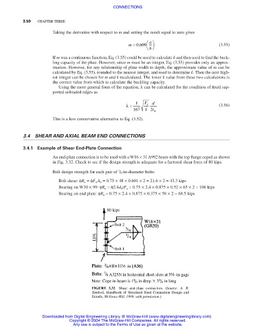
An end-plate connection is to be used with a W16 × 31 A992 beam with the top flange coped as shown
in Fig. 3.32. Check to see if the design strength is adequate for a factored shear force of 80 kips.
7
Bolt design strength for each pair of / 8-in-diameter bolts:
Bolt shear: φR n =φF n A b = 0.75 × 48 × 0.601 × 2 = 21.6 × 2 = 43.3 kips
Bearing on W30 × 99: φR n =φ2.4d b tF u = 0.75 × 2.4 × 0.875 × 0.52 × 65 × 2 = 106 kips
Bearing on end plate: φR n = 0.75 × 2.4 × 0.875 × 0.375 × 58 × 2 = 68.5 kips
FIGURE 3.32 Shear end-plate connection. (Source: A. R.
Tamboli, Handbook of Structural Steel Connection Design and
Details, McGraw-Hill, 1999, with permission.)
Downloaded from Digital Engineering Library @ McGraw-Hill (www.digitalengineeringlibrary.com)
Copyright © 2004 The McGraw-Hill Companies. All rights reserved.
Any use is subject to the Terms of Use as given at the website.