
Page 136 - Structural Steel Designers Handbook AISC, AASHTO, AISI, ASTM, and ASCE-07 Design Standards
P. 136
Brockenbrough_Ch03.qxd 9/29/05 5:05 PM Page 3.68
CONNECTIONS
3.68 CHAPTER THREE
line of bolts. The quantities T and F are for each of the two flanges. If M y is
the weak-axis applied moment, M f = M y /2 is the weak-axis applied moment
per flange. Taking moments about O gives a moment per flange of
M = T b − g − ε + T b + g − ε = Tb − 2ε( ) (3.64)
f
2 2 2 2
The bearing area is determined by requiring that the bearing stress reach its
design strength at the load F. Thus, 0.75(1.8F y )(2ε)t = F, and since from ver-
tical equilibrium F = 2T,
T = 0.75(1.8F y )tε (3.65)
Substituting in Eq. (3.64) to find M f = 0.75(1.8F y )tε(b − 2ε) and solving for
ε gives
b
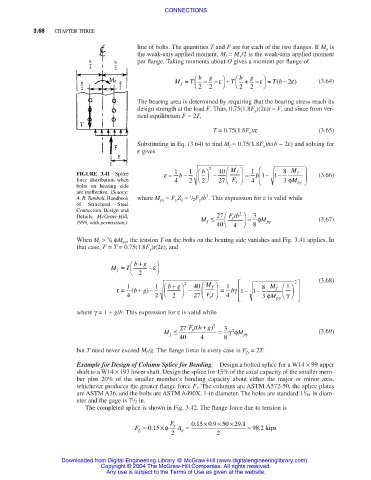
FIGURE 3.41 Splice ε = 1 b − 1 2 − 40 M f = 1 b 1 − 1 − 8 M f (3.66)
force distribution when 4 2 27 F y 4 3 φM py
2
bolts on bearing side
are ineffective. (Source:
2
1
A. R. Tamboli, Handbook where M py = F y Z y = / 2F y tb . This expression for ε is valid while
of Structural Steel
Connection Design and
2
Details, McGraw-Hill, M ≤ 27 Ftb = 3 φ
y
1999, with permission.) f M py (3.67)
40 4 8
3
When M f > / 8 φM py , the tension T on the bolts on the bearing side vanishes and Fig. 3.41 applies. In
that case, F = T = 0.75(1.8F y )t(2ε), and
+
M = T bg − ε
f
2
+
1
f
ε = 1 ( bg −) 1 bg 2 − 40 M = 1 b 1 − 1 − 8 M f 2 (3.68)
γ
+
γ
4 2 2 27 Ft 4 3 φ M
py
y
where γ= 1 + g/b. This expression for ε is valid while
+
(
M ≤ 27 Ft b g) 2 = 3 γφ M (3.69)
y
2
f
40 4 8 py
but T need never exceed M f /g. The flange force in every case is F fy = 2T.
Example for Design of Column Splice for Bending. Design a bolted splice for a W14 × 99 upper
shaft to a W14 × 193 lower shaft. Design the splice for 15% of the axial capacity of the smaller mem-
ber plus 20% of the smaller member’s bending capacity about either the major or minor axis,
whichever produces the greater flange force F f . The columns are ASTM A572-50, the splice plates
1
are ASTM A36, and the bolts are ASTM A490X, 1-in diameter. The holes are standard 1 / 16-in diam-
1
eter and the gage is 7 / 2 in.
The completed splice is shown in Fig. 3.42. The flange force due to tension is
×
×
F 015 × 09 50 291 .
.
.
F = 015 φ y A = = 98 2. kips
×
.
f t g
2 2
Downloaded from Digital Engineering Library @ McGraw-Hill (www.digitalengineeringlibrary.com)
Copyright © 2004 The McGraw-Hill Companies. All rights reserved.
Any use is subject to the Terms of Use as given at the website.