Page 140 - Structural Steel Designers Handbook AISC, AASHTO, AISI, ASTM, and ASCE-07 Design Standards
P. 140

Brockenbrough_Ch03.qxd  9/29/05  5:05 PM  Page 3.72


                                                        CONNECTIONS


                   3.72  CHAPTER THREE


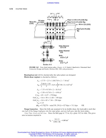
                                      FIGURE 3.43  Truss chord tension splice. (Source: A. R. Tamboli, Handbook of Structural Steel
                                      Connection Design and Details, McGraw-Hill, 1999, with permission.)

                                 Bearing/tear-out will be checked after the splice plates are designed.
                                 Block shear rupture is checked as follows:
                                              A nv = (7.75 − 2.5 × 1.0)0.710 × 2 = 7.46 in 2
                                                                 
                                                       − . ) 5
                                                   14
                                              A =   (.5 7  − . 05  ×1 0 .710 2   in 2
                                                                       ×= . 4 27
                                                  
                                                                 
                                               nt
                                                                 
                                                  
                                                       2
                                              A gv = 7.75 × 0.710 × 2 = 11.0 in 2
                                              A gt = 3.50 × 0.710 × 2 = 4.98 in 2
                                            F u A nt = 65 × 4.27 = 278 kips
                                          0.6F y A gv = 0.6 × 50 × 11.00 = 330 kips
                                          0.6F u A nv = 0.6 × 65 × 7.46 = 291 kips
                                              U bs = 1.0
                                             φR bs = 0.75[278 + min(330, 291)] = 427 kips > 311 kips  OK
                                 Flange Connection. Since the bolts are assumed to be in double shear, the load path is such that
                               one-half of the flange load goes into the outer plate, and one-half goes into the inner plates.
                                 Outer Plate: Gross and Net Area. Since the bolt gage is 7.5 in, try a plate 10.5 in wide. The gross
                               area in tension required is
                                                          A =  311 2 /  = 480  in 2
                                                                        .
                                                           gt
                                                              090 × 36
                                                               .

                           Downloaded from Digital Engineering Library @ McGraw-Hill (www.digitalengineeringlibrary.com)
                                      Copyright © 2004 The McGraw-Hill Companies. All rights reserved.
                                       Any use is subject to the Terms of Use as given at the website.
   135   136   137   138   139   140   141   142   143   144   145