
Page 231 - Structural Steel Designers Handbook AISC, AASHTO, AISI, ASTM, and ASCE-07 Design Standards
P. 231
Brockenbrough_Ch05.qxd 9/29/05 5:12 PM Page 5.11
CRITERIA FOR BUILDING DESIGN
CRITERIA FOR BUILDING DESIGN 5.11
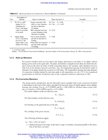
TABLE 5.2 Shear Lag Factors for Connections to Tension Members (Continued)
Description of
Case element Type of connection Shear lag factor U Example
2
7 W, M, S, or HP Flange connected with bf ≥ / 3d......U = 0.90 —
2
shapes (if U is three or more fasteners bf < / 3d........U = 0.85
calculated per per line in direction
Case 2, the larger of loading
value is permitted Web connected with four U = 0.70 —
to be used) or more fasteners in the
direction of loading
8 Single angles Four or more fasteners U = 0.80 —
(if U is calculated per line in direction of
per Case 2, the loading
larger value is per- Fewer than four fasteners U = 0.60 —
mitted to be used) per line in the direction
of loading
l = connection length.
Source: “Specification for Structural Steel Buildings,” American Institute of Steel Construction, Chicago, Ill., 2005, with permission.
5.3.3 Built-up Members
For tension members built up from plates and shapes, perforated cover plates or tie plates without
lacing can be used on the open sides. Tie plates should have a length not less than two-thirds the dis-
tance between the lines of welds or bolts connecting them to the member, and a thickness not less
1
than / 50th of the distance between such lines. Also, the longitudinal spacing of intermittent welds or
fasteners of tie plates should not exceed 6 in (150 mm). The longitudinal spacing and edge distance
of connectors is further limited by rules that apply to all connections (see Art. 5.9.7). It is considered
good practice to limit the slenderness ratio of any component between connections to 300.
5.3.4 Pin-Connected Members
The design tensile strength φ t P n and the allowable tensile strength P n /Ω t of pin-connected members
is determined as the least of the values calculated for the limit states of tensile rupture, shear rupture,
bearing, and yielding. Use φ t = 0.75 (LRFD) and Ω t = 2.00 (ASD) for all limit states except yield-
ing, for which φ t = 0.90 (LRFD) and Ω t = 1.67 (ASD).
For tensile rupture on the net effective area,
(5.15)
P n = 2tb eff F u
For shear rupture on the effective area,
(5.16)
P n = 0.6A sf F u
For bearing on the projected area of the pin,
(5.17)
P n = 1.8A pb F y
For yielding in the gross section,
(5.18)
P n = F y A g
The following definitions apply:
2
2
A sf = 2t(a + d/2), in (mm )
a = shortest distance from edge of pin hole to edge of member, measured parallel to the direc-
tion of the force, in (mm)
Downloaded from Digital Engineering Library @ McGraw-Hill (www.digitalengineeringlibrary.com)
Copyright © 2004 The McGraw-Hill Companies. All rights reserved.
Any use is subject to the Terms of Use as given at the website.