
Page 260 - Structural Steel Designers Handbook AISC, AASHTO, AISI, ASTM, and ASCE-07 Design Standards
P. 260
Brockenbrough_Ch05.qxd 9/29/05 5:12 PM Page 5.40
CRITERIA FOR BUILDING DESIGN
5.40 CHAPTER FIVE
Bolts used in combination with rivets, such as in alterations or rehab work, cannot be designed
to share the load with the rivets except as follows. When high-strength bolts are designed as slip-
critical connections, the bolts may be designed to share the load with the existing rivets.
Limitations on bolted and welded connections are as follows. The AISC Specification requires
that only pretensioned joints, slip-critical joints, or welds may be used for the following connections:
(1) Column splices in all multi-story structures over 125 ft (38 m) in height.
(2) Connections of all beams and girders to columns and any other beams and girders on which the
bracing of columns is dependent in structures over 125 ft (38 m) in height.
(3) In all structures carrying cranes of over five-ton (50 kN) capacity: roof truss splices and connec-
tions of trusses to columns, column splices, column bracing, knee braces, and crane supports.
(4) Connections for the support of machinery and other live loads that produce impact or reversal of load.
In all other cases, snug-tightened high-strength bolts and A307 bolts are acceptable.
5.9.2 Design Considerations for Welded Connections
Welds used in building construction are generally either groove welds, in which the weld is made in
a groove between connection elements, or fillet welds, in which a weld of generally triangular cross
section is made between intersecting surfaces of connection elements. Plug welds and slot welds are
also used for some purposes. In this case, the weld is made in a circular or an elongated hole, partly
or completely filling the hole, depending on depth.
For groove welds, the effective area for computation of design strength is the length of the
weld times the effective throat thickness. The effective throat thickness of a complete-joint-
penetration groove weld is the thickness of the thinner part joined. The effective throat thickness
of a partial-joint-penetration groove weld is given in Table 5.3. However, the joint must be
designed so the effective throat thickness is no less than the minimum values given in Table 5.4.
Generally, the effective throat size of a partial-joint-penetration weld is dependent on the process
used and the weld position. The designer should indicate either the effective throat required or the
weld strength required, so that the fabricator can detail the joint based on the weld process and
position that will be used.
Flare groove welds are welds made in a groove formed by a member with a curved surface in
contact with a planar member (flare bevel groove weld) or in a groove formed by two members
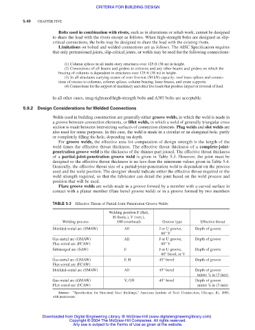
TABLE 5.3 Effective Throat of Partial-Joint-Penetration Groove Welds
Welding position F (flat),
H (horiz.), V (vert.),
Welding process OH (overhead) Groove type Effective throat
Shielded-metal arc (SMAW) All J or U groove, Depth of groove
60° V
Gas-metal arc (GMAW) All J or U groove, Depth of groove
Flux-cored arc (FCAW) 60° V
Submerged arc (SAW) F J or U groove, Depth of groove
60° bevel, or V
Gas-metal arc (GMAW) F, H 45° bevel Depth of groove
Flux-cored arc (FCAW)
Shielded-metal arc (SMAW) All 45° bevel Depth of groove
1
minus / 8 in (3 mm)
Gas-metal arc (GMAW) V, OH 45° bevel Depth of groove
1
Flux-cored arc (FCAW) minus / 8 in (3 mm)
Source: “Specification for Structural Steel Buildings,” American Institute of Steel Construction, Chicago, Ill,. 2005,
with permission.
Downloaded from Digital Engineering Library @ McGraw-Hill (www.digitalengineeringlibrary.com)
Copyright © 2004 The McGraw-Hill Companies. All rights reserved.
Any use is subject to the Terms of Use as given at the website.