
Page 67 - Sustainable On-Site CHP Systems Design, Construction, and Operations
P. 67
46 CHP B a s i c s
40
35
30
Electric efficiency (%) 25
20
15
10
5
0
0 1000 2000 3000 4000 5000 6000 7000
Rated power (kW)
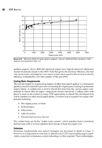
FIGURE 3-2 Effi ciency (HHV) of spark ignition engines. [Source: 2008 ASHRAE Handbook: HVAC
Systems and Equipment (Ref. 1).]
ignition engines, above 4000 kW electrical output have typical observed efficiencies
around 36 percent, based on the HHV. Note that given the electrical efficiency, the heat
rate can be easily calculated (or vice versa) as heat rate is equal to the inverse of electric
efficiency multiplied by 3413 (the number of Btu per kWh).
Cooling Water Requirements
The heat developed by reciprocating engines of either type (spark ignition or compression
ignition) must be rejected to prevent overheating the engine parts, leading to premature
engine failure. A coolant loop is used to absorb this heat from the various engine com-
ponents to ensure that all engine components remain functional. Cooling water with
glycol is used as the coolant in many CHP applications to absorb this developed heat
and to transfer it to other useful applications. A coolant loop is required for engine com-
ponents including
• The engine jacket, or block
• Turbochargers
• Aftercoolers
• Lube oil coolers
• Exhaust heat recovery devices
The coolant loop can be the “jacket water system” which transfers heat to beneficial
thermal uses and/or to heat rejection (heat dump) to keep the engine cool.
Emissions
Emissions fundamentals and control strategies are discussed in depth in Chap. 7;
however, it is important to note that, in almost every CHP reciprocating engine appli-
cation, some form of emission control technology is often required. These technologies,