
Page 160 - The Art and Science of Analog Circuit Design
P. 160
Tripping the Light Fantastic
The meeting went well, things got defined, and I took the backlight
problem. I still wasn't enthralled with backlights, but here was an almost
ideal customer falling in through the roof so there really wasn't any
choice.
Steve introduced me to Paul Donovan, who would become my primary
Apple contact. Donovan outlined the ideal backlight. It should have the
highest possible efficiency, that is, the highest possible display luminos-
ity with the lowest possible battery drain. Lamp intensity should be
smoothly and continuously variable over a wide range with no hysteresis,
or "pop-on," and should not be affected by supply voltage changes. RF
emissions should meet FCC and system requirements. Finally, parts
count and board space should be minimal. There was a board height re-
quirement of .25".
Getting Started—The Luddite Approach to Learning
I got started by getting a bunch of portable computers and taking them
apart. I must admit that the Luddite in me enjoyed throwing away most
of the computers while saving only their display sections. One thing I
immediately noticed was that almost all of them utilized a purchased,
board-level solution to backlight driving. Almost no one actually built the
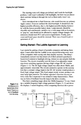
function. The circuits invariably took the form of an adjustable output
step-down switching regulator driving a high voltage DC-AC inverter
(Figure 11-2). The AC high-voltage output was often about 50kHz, and
approximately sinusoidal. The circuits seemed to operate on the assump-
tion that a constant voltage input to the DC-AC inverter would produce a
fixed, high voltage output. This fixed output would, in turn, produce con-
stant lamp light emission. The ballast capacitor's function was not en-
tirely clear, but I suspected it was related to lamp characteristics. There
was no form of feedback from the lamp to the drive circuitry.
Was there something magic about the 50kHz frequency? To see, I built
up a variable-frequency high voltage generator (Figure 11-3) and drove
Figure 11-2.
Architecture of a the displays. I varied frequency while comparing electrical drive power
typical lamp driver
board. There is no POWER BALLAST
form of feedback SWITCH CAPACITOR
from the lamp. •_ rYYY\_^__. H HI— u
X,
DC/AC
_L t T HIGH VOLTAGE LAMP
FEEDBACK CONVERTER
LJ
| -
i
REGULATOR
142