
Page 166 - The Art and Science of Analog Circuit Design
P. 166
Tripping the Light Fantastic
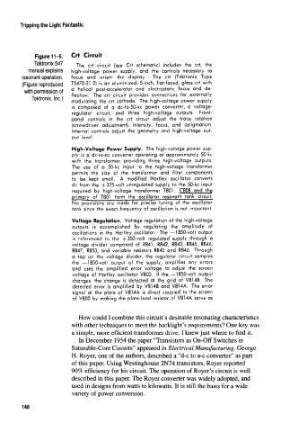
Figure 11-5. Crt Circuit
Tektronix 547 The crt circuit (see Crt schematic) includes the crt, the
manual explains high-voltage power supply, and the controls necessary to
resonant operation. focus and orient the display. The crt (Tektronix Type
(Figure reproduced T5470-31-2) is an aluminized, 5-inch, flat-faced, glass crt with
with permission of a helical post-accelerator and electrostatic focus and de-
flection. The crt circuit provides connections for externally
Tektronix, Inc.)
modulating the crt cathode. The high-voltage power supply
is composed of a dc-tp-50-kc power converter, a voltage-
regulator circuit, and three high-voltage outputs. Front-
panel controls in the crt circuit adjust the trace rotation
(screwdriver adjustment), intensity, focus, and astigmatism.
internal controls adjust the geometry and high-voltage out-
put level.
High-Voltage Power Supply. The high-voltage power sup-
ply is a dc-to-ac converter operating at approximately 50 kc
with the transformer providing three high-voltage outputs.
The use of a 50-kc input to the high-voltage transformer
permits the size of the transformer and filter components
to be kept small. A modified Hartley oscillator converts
dc from the +325-volt unregulated supply to the 50-kc input
required by high-voltage transformer T801. C.8Q8 and the
primary of T801 form the oscillator resonant tank circuit
No provisions are made for precise tuning of the oscillator
tank since the exact frequency of oscillation is not important,
Voltage Regulation. Voltage regulation of the high-voltage
outputs is accomplished by regulating the amplitude of
oscillations in the Hartley oscillator. The —1850-volt output
is referenced to the -f350-volt regulated supply through a
voltage divider composed of R841, R842, R843, R845, R846,
R847, R853, and variable resistors R840 and R846. Through
a tap on the voltage divider, the regulator circuit samples
the —1850-volt output of the supply, amplifies any errors
and uses the amplified error voltage to adjust the screen
voltage of Hartley oscillator V800. If the —1850-volt output
changes, the change is detected at the grid of V814B. The
detected error is amplified by V814B and V814A. The error
signal at the plate of V814A is direct coupled to the screen
of V800 by making the plate-load resistor of V814A serve as
How could I combine this circuit's desirable resonating characteristics
with other techniques to meet the backlight's requirements? One key was
a simple, more efficient transformer drive. I knew just where to find it.
In December 1954 the paper "Transistors as On-Off Switches in
Saturable-Core Circuits" appeared in Electrical Manufacturing. George
H. Royer, one of the authors, described a "d-c to a-c converter" as part
of this paper. Using Westinghouse 2N74 transistors, Royer reported
90% efficiency for his circuit. The operation of Royer's circuit is well
described in this paper. The Royer converter was widely adopted, and
used in designs from watts to kilowatts. It is still the basis for a wide
variety of power conversion.
148