
Page 242 - The Art of Designing Embedded Systems
P. 242
A Simple Drawing System 229
The Top Level Configuration Drawing (which is really a BOM) calls out
subassemblies by referring to each with a drawing number with a dash suf-
fix-a sort of pointer. Each subassembly contains pointers to parts or more
levels of indirection to further BOMs. This makes it easy to share drawings
between projects; you just have to monkey with the pointers. The dash
numbers insure that every configuration of a project is documented, not
just the overall PC layout.
BOM Format
BOMs are never “pictures” of anything-they are always just Bills of
Materials (Le., parts lists). The parts list includes every part needed to
build that subassembly. Some of the parts might refer to further sub-
assemblies.
The parts list of the BOM has the following fields:
Item number (starting at 1 and working up)
Quantity used, by dash number
Part (or drawing) number
Description
Reference tie., U number or whatever)
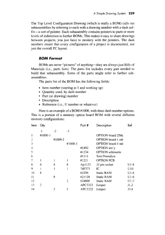
Here is an example of a BOM #IOOO, with three dash number options.
This is a portion of a memory option board BOM with several different
memory configurations:
I tern Qty Part # Description Ref
-1 -2 -3
I #1000-1 OPTION board 256k
7 #1000-2 OPTION board 1 mb
3 ## 1000-3 OPTION board 4 mb
4 #1892 OPTION ass’y
5 #I234 OPTION schematic
6 #I111 Test Procedure
7 1 1 I #I221 OPTION PCB
8 8 8 8 Apl123 32 pin socket u1-8
9 1 1 1 74F373 IC u10
10 8 62256 Static RAM u1-8
11 8 621 128 Static RAM U1-8
12 2 624000 Static RAM u1-2
13 1 APC3322 Jumper J1,2
L
14 2 2 APC3322 Jumper J3,4