
Page 165 - The Combined Finite-Discrete Element Method
P. 165
148 DEFORMABILITY OF DISCRETE ELEMENTS
These represent calculation of the traction forces on the surfaces
ˆ ˆ ˆ
˜
˜ i(det F)), j(det F) and k(det F) (4.85)
˜
The matrix form of traction force calculation is given by
ˆ ˆ ˆ
˜ ˜ ˜
x x x t xx t xy t xz
S ˆ ˜x S ˆ ˜y S ˆ ˜z i x j x k x
ˆ ˜ ˆ ˜ ˜ (det F) (4.86)
i
ˆ
S = S ˆ ˜x S ˆ ˜y S ˆ ˜z = t yx t yy t yz y j y k y
y
y
y
t zx t zy t zz
S ˆ ˜x S ˆ ˜y S ˆ ˆ ˜ ˆ ˜ ˆ ˜
z z z˜z i z j z k z
Thus, the first index indicates the direction of the stress component (global x, y or
z direction). The second index indicates the surface of the material element the stress
component is associated with (the surface that was initially normal to the initial x, y
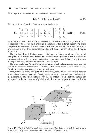
or z direction). The stress components of the first Piola-Kirchhoff stress are shown in
Figure 4.9.
The first Piola-Kirchhoff stress represents the traction force per unit area of the initial
configuration. However, when viewed in a deformed configuration it does not represent
stress per unit area. It represents traction force component per deformed area that was
initially a unit area, but after deformation it has changed.
The same can be said for the Cauchy stress tensor, which truly represents stress per unit
area of the deformed configuration. When the initial configuration is taken into account,
Cauchy stress does not represent stress per unit area.
Thus, when a deformed configuration is considered, stress per unit area for any material
point is best expressed using the Cauchy stress tensor and material element defined by
the global triad, but on a deformed body (i.e. the surfaces of the material element are
orthogonal to the unit vectors of global triad). The stress components associated with
~
i
~
j j
s xy ~ ˆ
~
k
i Deformed configuration
k Initial configuration
Figure 4.9 The first Piola-Kirchhoff stress components. Note that the material element is taken
in the initial configuration in the directions of the vectors of the local triad.