
Page 47 - The Combined Finite-Discrete Element Method
P. 47
30 INTRODUCTION
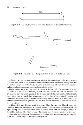
30 (m)
2.4 (m)
Figure 1.44 The simply supported beam after the release of the right-hand support.
(a) (b)
(c)
Figure 1.45 Failure (a) and subsequent motion (b and c) of the broken beam.
In Figure 1.46, the collapse sequence of a bridge due to the impact of a heavy vehicle
is shown. The result of the combined finite-discrete element simulation clearly indicates
the collapse sequence of the bridge together with the time intervals for each sequence
and the total time necessary for the collapse of the bridge.
Similar failure of a retaining wall is shown in Figure 1.47. The pressure of water
saturated clay results in overturning of the wall, and finally, its free fall towards the
ground. The clay has disintegrated in the process. Despite the very coarse finite element
mesh being used to model clay, a combination of the loss of its structural integrity and
consequent increased pressure against the retaining wall has resulted in wall overturning
and the clay further disintegrating until the wall reaches the state of free rotation about
the foundation.
In Figure 1.48 the chimney stack is shown. After the base was blasted away, the
combined finite-discrete element simulation shows a chimney stack leaning towards the
right. Finally, due to the combined effect of inertia forces and self-weight, it breaks in
the middle part and falls freely towards the ground until it crashes against the ground.
It is worth mentioning that the combined finite-discrete element simulation has correctly
predicted all three stages of the demolition process: