
Page 62 - The Combined Finite-Discrete Element Method
P. 62
IMPLEMENTATION DETAILS FOR DISCRETISED CONTACT FORCE IN 2D 45
B
0
2
A 1
A 2 3
A
A 3
1
Target Contactor
C
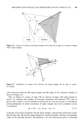
Figure 2.6 Contact of contactor and target triangles and contact of an edge of a contactor triangle
with a target triangle.
0
B
P 2 v
0 2
P 0 P 1
A
y p
r A 1
1
r 1
x
u
Figure 2.7 Distribution of contact force between the target triangle and an edge of contac-
tor triangle.
with interactions between the target triangle and the edges of the contactor triangle, as
shown in Figure 2.6.
Thus, in Figure 2.7 contact of edge AB of contactor triangle with target triangle is
shown. To minimise the number of necessary operations and therefore CPU time to
process this contact, a local coordinate system given by local axes u and v is introduced,
and transformation of nodal coordinates of target triangle into local coordinate system
is performed:
p i = ((r i − r A ) · u,(r i − r A ) · v) (2.31)
Using the local nodal coordinates for the target triangle, characteristic intersection points
between the edge AB and the target triangle are obtained together with the corresponding
values of the potential function. The potential ϕ for each intersection point is calculated