
Page 63 - The Combined Finite-Discrete Element Method
P. 63
46 PROCESSING OF CONTACT INTERACTION
by interpolation between the central node (node 3, where the potential is equal to 1) and
the corresponding edge node (nodes 0,1 or 2, where potential is equal to zero) for each
intersection point.
The total contact force exerted by the target triangle onto the edge AB is given by the
area of the diagram of potential over the edge AB, i.e.
1 L
f c,AB = u pϕ(v)dv (2.32)
u 2 0
2
where p is the penalty term, while the term u comes from the fact that vectors u and v
are not unit vectors. This is computationally convenient as, that evaluation of the integral
(2.32) does not involve a square root. In addition, in between the intersection points the
potential ϕ is given by straight lines, which reduces integration to area calculation, as
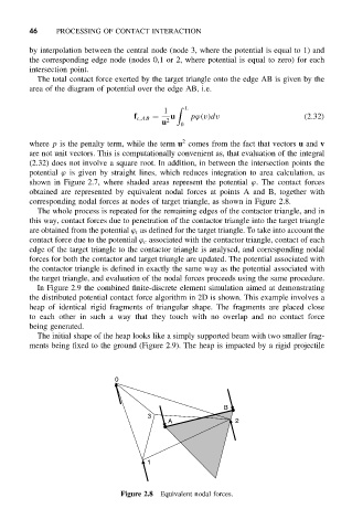
shown in Figure 2.7, where shaded areas represent the potential ϕ. The contact forces
obtained are represented by equivalent nodal forces at points A and B, together with
corresponding nodal forces at nodes of target triangle, as shown in Figure 2.8.
The whole process is repeated for the remaining edges of the contactor triangle, and in
this way, contact forces due to penetration of the contactor triangle into the target triangle
are obtained from the potential ϕ t as defined for the target triangle. To take into account the
contact force due to the potential ϕ c associated with the contactor triangle, contact of each
edge of the target triangle to the contactor triangle is analysed, and corresponding nodal
forces for both the contactor and target triangle are updated. The potential associated with
the contactor triangle is defined in exactly the same way as the potential associated with
the target triangle, and evaluation of the nodal forces proceeds using the same procedure.
In Figure 2.9 the combined finite-discrete element simulation aimed at demonstrating
the distributed potential contact force algorithm in 2D is shown. This example involves a
heap of identical rigid fragments of triangular shape. The fragments are placed close
to each other in such a way that they touch with no overlap and no contact force
being generated.
The initial shape of the heap looks like a simply supported beam with two smaller frag-
ments being fixed to the ground (Figure 2.9). The heap is impacted by a rigid projectile
0
B
3
A 2
1
Figure 2.8 Equivalent nodal forces.