
Page 130 - The Definitive Guide to Building Java Robots
P. 130
Preston_5564C04.fm Page 111 Wednesday, October 5, 2005 7:22 AM
CHAPTER 4 ■ SENSORS 111
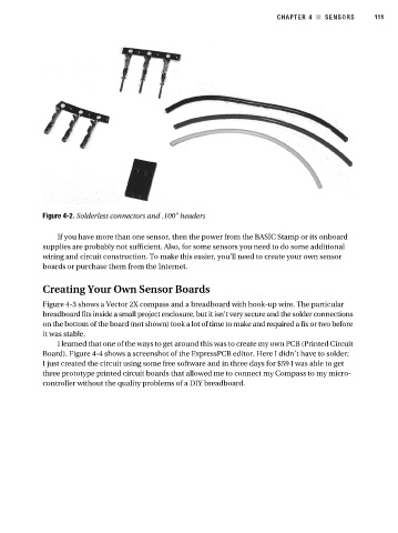
Figure 4-2. Solderless connectors and .100” headers
If you have more than one sensor, then the power from the BASIC Stamp or its onboard
supplies are probably not sufficient. Also, for some sensors you need to do some additional
wiring and circuit construction. To make this easier, you’ll need to create your own sensor
boards or purchase them from the Internet.
Creating Your Own Sensor Boards
Figure 4-3 shows a Vector 2X compass and a breadboard with hook-up wire. The particular
breadboard fits inside a small project enclosure, but it isn’t very secure and the solder connections
on the bottom of the board (not shown) took a lot of time to make and required a fix or two before
it was stable.
I learned that one of the ways to get around this was to create my own PCB (Printed Circuit
Board). Figure 4-4 shows a screenshot of the ExpressPCB editor. Here I didn’t have to solder;
I just created the circuit using some free software and in three days for $59 I was able to get
three prototype printed circuit boards that allowed me to connect my Compass to my micro-
controller without the quality problems of a DIY breadboard.