
Page 132 - The Definitive Guide to Building Java Robots
P. 132
Preston_5564C04.fm Page 113 Wednesday, October 5, 2005 7:22 AM
CHAPTER 4 ■ SENSORS 113
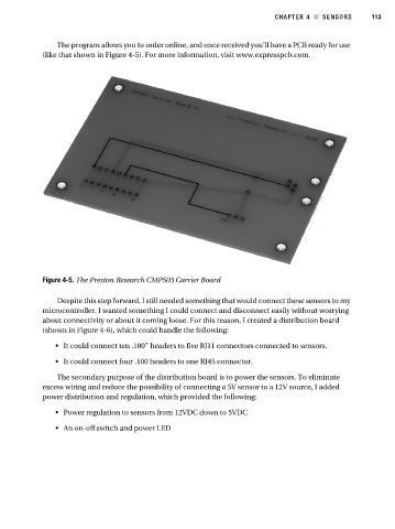
The program allows you to order online, and once received you’ll have a PCB ready for use
(like that shown in Figure 4-5). For more information, visit www.expresspcb.com.
Figure 4-5. The Preston Research CMPS03 Carrier Board
Despite this step forward, I still needed something that would connect these sensors to my
microcontroller. I wanted something I could connect and disconnect easily without worrying
about connectivity or about it coming loose. For this reason, I created a distribution board
(shown in Figure 4-6), which could handle the following:
• It could connect ten .100” headers to five RJ11 connectors connected to sensors.
• It could connect four .100 headers to one RJ45 connector.
The secondary purpose of the distribution board is to power the sensors. To eliminate
excess wiring and reduce the possibility of connecting a 5V sensor to a 12V source, I added
power distribution and regulation, which provided the following:
• Power regulation to sensors from 12VDC down to 5VDC
• An on-off switch and power LED