
Page 426 - The Engineering Guide to LEED-New Construction Sustainable Construction for Engineers
P. 426
386 Cha pte r T e n
vehicular and other uses. There is a need to be able to model the various pervious
concrete systems and their impacts on hydrology and pollutant transport.
Many studies show that the infiltration rate through the pervious concrete itself is
usually much greater than that through any natural soil type. The infiltration rate may
therefore be limited by the subbase and subgrade below. Typically, pervious concrete
can be placed directly over well-drained soils such as sands, but should be placed over
additional storage subbases such as gravel, when used over poorly drained soils such
as clays. This allows for additional time for the stormwater to infiltrate into the ground
instead of running off. Usually overflow pipes are also included for stormwater
management purposes for large storms.
Based on the LEED-NC 2.2 and 2009 Reference Guides, pervious concrete areas can
be considered to be pervious. However, there are also local or state interpretations of
how to count the highly pervious concrete and asphalt pavements with respect to
imperviousness, and these must be taken into consideration for local requirements and
interpretations. LEED usually defers to the local code if it is more stringent than the
LEED credit criteria. For example, in North Carolina, pervious concrete and porous
asphalt may count toward 40 to 60 percent as managed grass with respect to percent
imperviousness for a site.
A pervious concrete application is a good method by which to use the simple box
model to estimate runoff from a site. Consider a system consisting of pervious concrete
with a gravel subbase and then soil below and with the pavement system essentially
flat. This system receives upslope runoff and direct rainfall. The condition being
modeled is a storm with no antecedent precipitation (storage volume initially empty)
and during the time when evaporation can be assumed negligible (during the
precipitation event). There are two questions being asked:
• How long until the onset of runoff?
• After the storage volume is full, what is the steady-state rate of runoff?
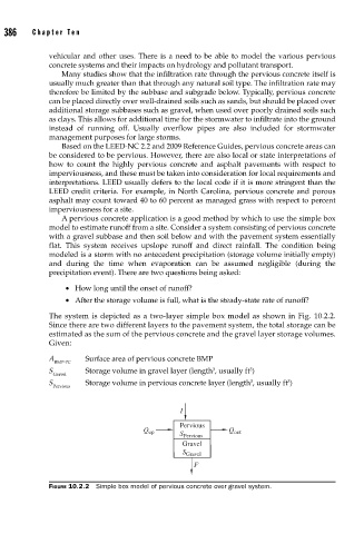
The system is depicted as a two-layer simple box model as shown in Fig. 10.2.2.
Since there are two different layers to the pavement system, the total storage can be
estimated as the sum of the pervious concrete and the gravel layer storage volumes.
Given:
A Surface area of pervious concrete BMP
BMP-PC
3
3
S Storage volume in gravel layer (length , usually ft )
Gravel
3
3
S Storage volume in pervious concrete layer (length , usually ft )
Pervious
I
Pervious
Q up Q out
S Pervious
Gravel
S Gravel
F
FIGURE 10.2.2 Simple box model of pervious concrete over gravel system.